A High-Efficiency Rotary Air Shower (Utility Model CN 210304872 U)
The present utility model provides a high-efficiency rotary air shower, comprising a box body, wherein door panels are provided at both the front and rear ends of the box body, a fan is...
Abstract
The present utility model provides a high-efficiency rotary air shower, comprising a box body, wherein door panels are provided at both the front and rear ends of the box body, a fan is provided at a top end of the box body, a filter tank is provided at a lower side of the fan, a first filter screen and a second filter screen are arranged in the filter tank, a first air discharge assembly and a second air discharge assembly are arranged on both sides inside the box body, an infrared emitter is fixed on one side of the first air discharge assembly, an infrared receiver is fixed on one side of the second air discharge assembly, a rotary motor is further provided at the bottom of an inner side of the box body, an output end of the rotary motor is connected to a rotating plate, a plurality of support rods are connected to the rotating plate, an arc-shaped handrail rod is connected to upper ends of the support rods, the arc-shaped handrail rod is provided with a handrail portion, an interior of the handrail portion is of a hollow structure, a plurality of ventilation holes are provided on both sides of an upper end of the handrail portion, and a third air discharge assembly is connected to a lower end of the handrail portion. The air shower of the present utility model has a good cleaning effect and high dust removal efficiency.
Patent Information
| Item | Detail |
|---|---|
| Issuing authority | National Intellectual Property Administration of the People’s Republic of China (CNIPA) |
| Document type | Utility Model Patent |
| Authorization publication number | CN 210304872 U |
| Authorization publication date | 2020.04.14 |
| Application number | 201920997733.5 |
| Filing date | 2019.06.28 |
| Patentee | Dongguan Pengchi Purification Technology Co., Ltd. |
| Address | Tangyilangwei Road, Tangjiao Village, Chashan Town, Dongguan City, Guangdong Province 523378, China |
| Inventors | Hu Guopeng |
| Patent agency | Dongguan Yongqiao Intellectual Property Agency (General Partnership) 44400 |
| Patent agent | He Xinhua |
| International Patent Classification (IPC) | B08B 5/02(2006.01); B08B 13/00(2006.01) |
| Title of utility model | A High-Efficiency Rotary Air Shower |
Claims
-
A high-efficiency rotary air shower, comprising:
- a box body (1), door panels (11) being provided at both front and rear ends of the box body (1);
- a fan (2) provided at a top end of the box body (1), a filter tank (12) being provided at a lower side of the fan (2), a first filter screen (3) and a second filter screen (4) being successively arranged in the filter tank (12) from bottom to top;
- a first air discharge assembly (5) and a second air discharge assembly (6) arranged on both sides inside the box body (1), an infrared emitter (71) being fixed on one side of the first air discharge assembly (5), and an infrared receiver (72) opposite to the infrared emitter (71) being fixed on one side of the second air discharge assembly (6);
- a rotary motor (81) further provided at the bottom of an inner side of the box body (1), an output end of the rotary motor (81) being connected to a rotating plate (82), a plurality of support rods (83) being connected to the rotating plate (82), an arc-shaped handrail rod (84) being connected to upper ends of the support rods (83), the arc-shaped handrail rod (84) being provided with a handrail portion (841), an interior of the handrail portion (841) being of a hollow structure, a plurality of ventilation holes (842) being provided on both sides of an upper end of the handrail portion (841); and
- a third air discharge assembly (9) connected to a lower end of the handrail portion (841).
-
The high-efficiency rotary air shower according to claim 1, characterized in that the first air discharge assembly (5) comprises a first blower (51), a first air pipe (52) connected to an air outlet of the first blower (51), and a plurality of first spray nozzles (53) connected to the first air pipe (52).
-
The high-efficiency rotary air shower according to claim 1, characterized in that the second air discharge assembly (6) comprises a second blower (61), a second air pipe (62) connected to an air outlet of the second blower (61), and a plurality of second spray nozzles (63) connected to the second air pipe (62).
-
The high-efficiency rotary air shower according to claim 1, characterized in that the third air discharge assembly (9) comprises a third blower (91) fixed between the two support rods (83), and a third air pipe (92) connected to an air outlet of the third blower (91), an upper end of the third air pipe (92) being connected in communication with the handrail portion (841).
-
The high-efficiency rotary air shower according to claim 1, characterized in that the first filter screen (3) and the second filter screen (4) are both textile fiber filter screens.
Description
TECHNICAL FIELD
[0001] The present utility model relates to the field of air showers, and in particular to a high-efficiency rotary air shower.
BACKGROUND ART
[0002] An air shower is a type of local purification equipment with relatively high versatility, installed between a clean room and a non-clean room. When persons and goods need to enter a clean area, they need to be blown and showered by the air shower, and the clean air blown out by the air shower can remove dust carried by the persons and goods, effectively blocking or reducing dust sources from entering the clean area. Air showers in the prior art generally have the problems of poor cleaning effect and low dust removal efficiency.
SUMMARY OF THE UTILITY MODEL
[0003] In view of the above problems, the present utility model provides a high-efficiency rotary air shower, which has a good cleaning effect and high dust removal efficiency.
[0004] To achieve the above object, the present utility model solves the above problems by means of the following technical solutions:
[0005] A high-efficiency rotary air shower, comprising a box body, wherein door panels are provided at both the front and rear ends of the box body, a fan is provided at a top end of the box body, a filter tank is provided at a lower side of the fan, a first filter screen and a second filter screen are successively arranged in the filter tank from bottom to top, a first air discharge assembly and a second air discharge assembly are arranged on both sides inside the box body, an infrared emitter is fixed on one side of the first air discharge assembly, an infrared receiver is fixed on one side of the second air discharge assembly, a rotary motor is further provided at the bottom of an inner side of the box body, an output end of the rotary motor is connected to a rotating plate, a plurality of support rods are connected to the rotating plate, an arc-shaped handrail rod is connected to upper ends of the support rods, the arc-shaped handrail rod is provided with a handrail portion, an interior of the handrail portion is of a hollow structure, a plurality of ventilation holes are provided on both sides of an upper end of the handrail portion, and a third air discharge assembly is connected to a lower end of the handrail portion.
[0006] Specifically, the first air discharge assembly comprises a first blower, a first air pipe connected to an air outlet of the first blower, and a plurality of first spray nozzles connected to the first air pipe.
[0007] Specifically, the second air discharge assembly comprises a second blower, a second air pipe connected to an air outlet of the second blower, and a plurality of second spray nozzles connected to the second air pipe.
[0008] Specifically, the third air discharge assembly comprises a third blower fixed between the two support rods, and a third air pipe connected to an air outlet of the third blower, an upper end of the third air pipe being connected in communication with the handrail portion.
[0009] Specifically, the first filter screen and the second filter screen are both textile fiber filter screens.
[0010] The present utility model has the following beneficial effects:
[0011] First, the air shower provided by the present utility model is additionally provided with a rotatable device; a user may stand on the rotating plate with the hands holding the handrail portion of the arc-shaped handrail rod, and can rotate for multiple turns inside the box body through rotation of the rotary motor, so that omnidirectional dust removal is achieved with high dust removal efficiency, without the user rotating for multiple turns by himself, and the degree of automation is high;
[0012] Second, an interior of the handrail portion is of a hollow structure, a plurality of ventilation holes are provided on both sides of an upper end of the handrail portion, and a third air discharge assembly is connected to a lower end of the handrail portion; the third air discharge assembly enables the ventilation holes to continuously discharge air, so that sufficient air-borne dust removal can be performed on the hands within a period of time before the user grips the handrail portion and after the user releases the handrail portion, and the cleaning effect is good.
BRIEF DESCRIPTION OF THE DRAWINGS
[0013] FIG. 1 is a structural schematic view of the high-efficiency rotary air shower of the present utility model.
[0014] FIG. 2 is a cross-sectional view taken along plane A-A in FIG. 1.
[0015] FIG. 3 is a structural schematic view of the rotary motor, the rotating plate, the support rods, the arc-shaped handrail rod and the third air discharge assembly in the present utility model.
[0016] FIG. 4 is a cross-sectional view of the arc-shaped handrail rod in the present utility model.
[0017] The reference signs are as follows: box body 1; door panel 11; filter tank 12; fan 2; first filter screen 3; second filter screen 4; first air discharge assembly 5; first blower 51; first air pipe 52; first spray nozzle 53; second air discharge assembly 6; second blower 61; second air pipe 62; second spray nozzle 63; infrared emitter 71; infrared receiver 72; rotary motor 81; rotating plate 82; support rod 83; arc-shaped handrail rod 84; handrail portion 841; ventilation hole 842; third air discharge assembly 9; third blower 91; third air pipe 92.
DETAILED DESCRIPTION OF EMBODIMENTS
[0018] The present utility model will be described in further detail below in conjunction with the embodiments and the accompanying drawings, but the embodiments of the present utility model are not limited thereto.
[0019] As shown in FIGS. 1-4:
[0020] A high-efficiency rotary air shower comprises a box body 1; door panels 11 are provided at both the front and rear ends of the box body 1; a fan 2 is provided at a top end of the box body 1, a filter tank 12 is provided at a lower side of the fan 2, and a first filter screen 3 and a second filter screen 4 are successively arranged in the filter tank 12 from bottom to top; a first air discharge assembly 5 and a second air discharge assembly 6 are arranged on both sides inside the box body 1; an infrared emitter 71 is fixed on one side of the first air discharge assembly 5, and an infrared receiver 72 opposite to the infrared emitter 71 is fixed on one side of the second air discharge assembly 6; the infrared emitter 71 and the infrared receiver 72 cooperate to sense whether a person or an object passes between them; the infrared emitter 71 continuously emits infrared rays; when there is no obstruction between the infrared emitter 71 and the infrared receiver 72, the infrared receiver 72 can receive an optical signal; when a person or an object blocks between the infrared emitter 71 and the infrared receiver 72, the infrared receiver 72 cannot receive an optical signal, and the infrared receiver 72 feeds the signal back to a corresponding control system, which then issues instructions for the operation of the fan 2, the first blower 51, the second blower 61 and the third blower 91 at corresponding positions; a rotary motor 81 is further provided at the bottom of an inner side of the box body 1; an output end of the rotary motor 81 is connected to a rotating plate 82; a plurality of support rods 83 are connected to the rotating plate 82, and an arc-shaped handrail rod 84 is connected to upper ends of the support rods 83; the arc-shaped handrail rod 84 is provided with a handrail portion 841; after opening the front door panel 11 and entering the box body 1, a user may stand on the rotating plate 82 with the hands holding the handrail portion 841 of the arc-shaped handrail rod 84, and can rotate for multiple turns inside the box body 1 through rotation of the rotary motor 81; then, under control of the rotary motor 81, a notch of the arc-shaped handrail rod 84 moves to the side of the rear door panel 11, and the user exits through the rear door panel 11; then the rotary motor 81 controls the arc-shaped handrail rod 84 to reset, so that the notch of the arc-shaped handrail rod 84 moves to the side of the front door panel 11, thereby achieving an omnidirectional dust removal effect with high dust removal efficiency, without the user rotating for multiple turns by himself, and the degree of automation is high; an interior of the handrail portion 841 is of a hollow structure, a plurality of ventilation holes 842 are provided on both sides of an upper end of the handrail portion 841, and a third air discharge assembly 9 is connected to a lower end of the handrail portion 841, so that sufficient air-borne dust removal can be performed on the hands within a period of time before the user grips the handrail portion 841 and after the user releases the handrail portion 841, and the cleaning effect is good.
[0021] Preferably, the first air discharge assembly 5 comprises a first blower 51, a first air pipe 52 connected to an air outlet of the first blower 51, and a plurality of first spray nozzles 53 connected to the first air pipe 52.
[0022] Preferably, the second air discharge assembly 6 comprises a second blower 61, a second air pipe 62 connected to an air outlet of the second blower 61, and a plurality of second spray nozzles 63 connected to the second air pipe 62.
[0023] Preferably, the third air discharge assembly 9 comprises a third blower 91 fixed between the two support rods 83, and a third air pipe 92 connected to an air outlet of the third blower 91, an upper end of the third air pipe 92 being connected in communication with the handrail portion 841.
[0024] Preferably, the first filter screen 3 and the second filter screen 4 are both textile fiber filter screens, which have a good filtering effect and are easy to clean.
[0025] The above embodiments merely express one embodiment of the present utility model, and the description thereof is relatively specific and detailed, but it should not be construed as limiting the patent scope of the present utility model. It should be noted that those of ordinary skill in the art may make several modifications and improvements without departing from the concept of the present utility model, and these shall all fall within the protection scope of the present utility model. Therefore, the protection scope of the present utility model patent shall be defined by the appended claims.
Drawings
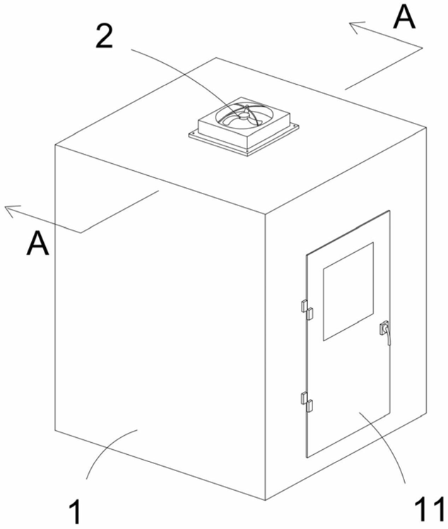 FIG. 1 — Structural schematic view of the high-efficiency rotary air shower
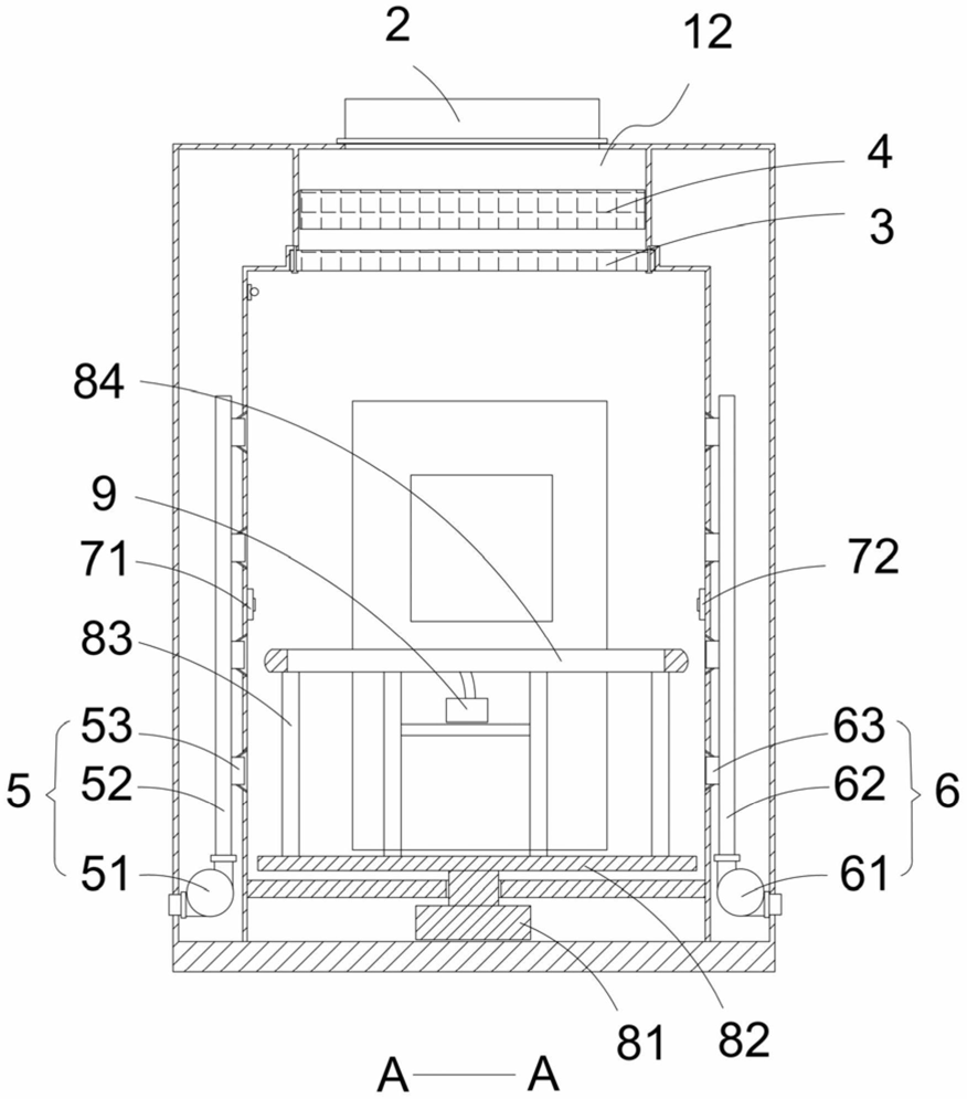 FIG. 2 — Cross-sectional view taken along plane A-A in FIG. 1
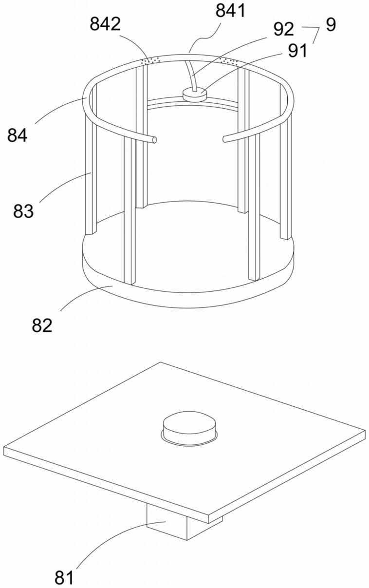 FIG. 3 — Structural schematic view of the rotary motor, rotating plate, support rods, arc-shaped handrail rod and third air discharge assembly
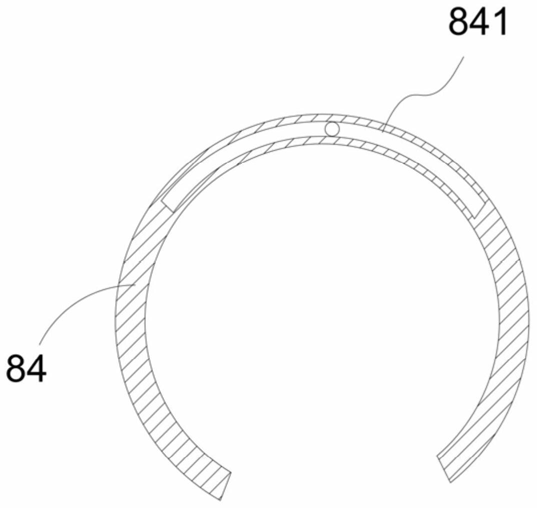 FIG. 4 — Cross-sectional view of the arc-shaped handrail rod