A Knee-Operated Hand-Washing Basin (Utility Model CN 210315823 U)
The present utility model provides a knee-operated hand-washing basin, comprising a base and a back plate, wherein a hand-washing basin is provided on the base, a water tap is installed on...
Abstract
The present utility model provides a knee-operated hand-washing basin, comprising a base and a back plate, wherein a hand-washing basin is provided on the base, a water tap is installed on an upper side of the hand-washing basin, an electrically controlled valve is connected to a bottom of the water tap, a knee-controlled rocker panel is provided at a front end of the base, a lower end of the knee-controlled rocker panel is rotationally connected to the base, a knee-control assembly is provided on an inner side of an upper end of the knee-controlled rocker panel, and the knee-control assembly is electrically connected to the electrically controlled valve; a foot-operated rocker panel is further provided at the front end of the base, a lower end of the foot-operated rocker panel is rotationally connected to the base, and a foot-control assembly is provided on an inner side of an upper end of the foot-operated rocker panel; a guide rail and an air cylinder are further provided in the base, a movable box is slidably connected to the guide rail, an output end of the air cylinder is fixedly connected to one end of the movable box, and the foot-control assembly is electrically connected to the air cylinder. With the knee-operated hand-washing basin of the present utility model, a user may stand in front of the hand-washing basin and control on/off of the water tap by means of the knee, avoiding secondary contamination of the hands after hand washing.
Patent Information
| Item | Detail |
|---|---|
| Issuing authority | National Intellectual Property Administration of the People’s Republic of China (CNIPA) |
| Document type | Utility Model Patent |
| Authorization publication number | CN 210315823 U |
| Authorization publication date | 2020.04.14 |
| Application number | 201920993181.0 |
| Filing date | 2019.06.28 |
| Patentee | Dongguan Pengchi Purification Technology Co., Ltd. |
| Address | Tangyilangwei Road, Tangjiao Village, Chashan Town, Dongguan City, Guangdong Province 523378, China |
| Inventors | Hu Guopeng |
| Patent agency | Dongguan Yongqiao Intellectual Property Agency (General Partnership) 44400 |
| Patent agent | He Xinhua |
| International Patent Classification (IPC) | E03C 1/05(2006.01); B65F 1/14(2006.01) |
| Title of utility model | A Knee-Operated Hand-Washing Basin |
Claims
-
A knee-operated hand-washing basin, comprising:
- a base (1) and a back plate (2), a hand-washing basin (3) being provided on the base (1), a water tap (4) being installed on an upper side of the hand-washing basin (3), and an electrically controlled valve (41) being connected to a bottom of the water tap (4);
- characterized in that a knee-controlled rocker panel (11) is provided at a front end of the base (1), a lower end of the knee-controlled rocker panel (11) being rotationally connected to the base (1), a knee-control assembly (5) being provided on an inner side of an upper end of the knee-controlled rocker panel (11), and the knee-control assembly (5) being electrically connected to the electrically controlled valve (41);
- a foot-operated rocker panel (12) is further provided at the front end of the base (1), a lower end of the foot-operated rocker panel (12) being rotationally connected to the base (1), and a foot-control assembly (6) being provided on an inner side of an upper end of the foot-operated rocker panel (12);
- a guide rail (13) and an air cylinder (14) are further provided in the base (1), a movable box (15) being slidably connected to the guide rail (13), an output end of the air cylinder (14) being fixedly connected to one end of the movable box (15), and the foot-control assembly (6) being electrically connected to the air cylinder (14).
-
The knee-operated hand-washing basin according to claim 1, characterized in that a trash can (16) is placed in the movable box (15).
-
The knee-operated hand-washing basin according to claim 1, characterized in that the knee-control assembly (5) comprises a first pressing block (51) fixed on the inner side of the upper end of the knee-controlled rocker panel (11), a first spring (52) sleeved on an outer side of the first pressing block (51), and a first switch (53) located on one side of the first pressing block (51), the first switch (53) being electrically connected to the electrically controlled valve (41).
-
The knee-operated hand-washing basin according to claim 3, characterized in that a spring latch pin (17) is further provided at a top end of the knee-controlled rocker panel (11).
-
The knee-operated hand-washing basin according to claim 1, characterized in that the foot-control assembly (6) comprises a second pressing block (61) fixed on the inner side of the upper end of the foot-operated rocker panel (12), a second spring (62) sleeved on an outer side of the second pressing block (61), and a second switch (63) located on one side of the second pressing block (61), the second switch (63) being electrically connected to the air cylinder (14).
-
The knee-operated hand-washing basin according to claim 1, characterized in that a mirror (21) and a light source (22) are further installed on the back plate (2), and a key switch (18) electrically connected to the light source (22) is provided on one side of the hand-washing basin (3).
Description
TECHNICAL FIELD
[0001] The present utility model relates to the field of medical equipment, and in particular to a knee-operated hand-washing basin.
BACKGROUND ART
[0002] In hospitals, doctors often need to wash and disinfect their hands before performing an operation, and in order to keep the hands clean, generally the hands cannot touch other objects after washing. At present, ordinary water taps are commonly provided in hospital hand-washing basins, and secondary contamination of the hands is liable to occur when the water tap is turned off. In addition, a trash can is usually placed beside the hand-washing basin; however, a trash can placed indoors for a long time is liable to cause indoor dust to fly about or bacteria to breed. These problems all urgently need to be solved.
SUMMARY OF THE UTILITY MODEL
[0003] In view of the above problems, the present utility model provides a knee-operated hand-washing basin, with which a user may stand in front of the hand-washing basin and control on/off of the water tap by means of the knee, avoiding secondary contamination of the hands after hand washing.
[0004] To achieve the above object, the present utility model solves the above problems by means of the following technical solutions:
[0005] A knee-operated hand-washing basin, comprising a base and a back plate, wherein a hand-washing basin is provided on the base, a water tap is installed on an upper side of the hand-washing basin, an electrically controlled valve is connected to a bottom of the water tap, a knee-controlled rocker panel is provided at a front end of the base, a lower end of the knee-controlled rocker panel is rotationally connected to the base, a knee-control assembly is provided on an inner side of an upper end of the knee-controlled rocker panel, and the knee-control assembly is electrically connected to the electrically controlled valve; a foot-operated rocker panel is further provided at the front end of the base, a lower end of the foot-operated rocker panel is rotationally connected to the base, and a foot-control assembly is provided on an inner side of an upper end of the foot-operated rocker panel; a guide rail and an air cylinder are further provided in the base, a movable box is slidably connected to the guide rail, an output end of the air cylinder is fixedly connected to one end of the movable box, and the foot-control assembly is electrically connected to the air cylinder.
[0006] Specifically, a trash can is placed in the movable box.
[0007] Specifically, the knee-control assembly comprises a first pressing block fixed on the inner side of the upper end of the knee-controlled rocker panel, a first spring sleeved on an outer side of the first pressing block, and a first switch located on one side of the first pressing block, the first switch being electrically connected to the electrically controlled valve.
[0008] Specifically, a spring latch pin is further provided at a top end of the knee-controlled rocker panel.
[0009] Specifically, the foot-control assembly comprises a second pressing block fixed on the inner side of the upper end of the foot-operated rocker panel, a second spring sleeved on an outer side of the second pressing block, and a second switch located on one side of the second pressing block, the second switch being electrically connected to the air cylinder.
[0010] Specifically, a mirror and a light source are further installed on the back plate, and a key switch electrically connected to the light source is provided on one side of the hand-washing basin.
[0011] The present utility model has the following beneficial effects:
[0012] First, the knee-operated hand-washing basin provided by the present utility model is additionally provided with the knee-controlled rocker panel, the knee-control assembly and the electrically controlled valve; a user may stand in front of the hand-washing basin and press the knee-controlled rocker panel with the knee, so that the electrically controlled valve controls on/off of the water tap, avoiding secondary contamination of the hands after hand washing;
[0013] Second, a foot-operated rocker panel and a foot-control assembly are added; the foot can be used to step on the foot-operated rocker panel, so as to control starting of the air cylinder; the output end of the air cylinder is connected to a movable box, and a trash can is placed in the movable box; tissues used after hand washing and hand wiping can be discarded into the trash can, and then the air cylinder drives the movable box into the base, avoiding the problem that the trash can is exposed indoors, causing indoor dust to fly about or bacteria to breed.
BRIEF DESCRIPTION OF THE DRAWINGS
[0014] FIG. 1 is a front view of the knee-operated hand-washing basin of the present utility model.
[0015] FIG. 2 is a cross-sectional view taken along plane C-C in FIG. 1.
[0016] FIG. 3 is an enlarged view of part A in FIG. 2.
[0017] FIG. 4 is an enlarged view of part B in FIG. 2.
[0018] FIG. 5 is a structural schematic view of the guide rail, the air cylinder, the movable box and the trash can in the present utility model.
[0019] The reference signs are as follows: base 1; knee-controlled rocker panel 11; foot-operated rocker panel 12; guide rail 13; air cylinder 14; movable box 15; trash can 16; spring latch pin 17; key switch 18; back plate 2; mirror 21; light source 22; hand-washing basin 3; water tap 4; electrically controlled valve 41; knee-control assembly 5; first pressing block 51; first spring 52; first switch 53; foot-control assembly 6; second pressing block 61; second spring 62; second switch 63.
DETAILED DESCRIPTION OF EMBODIMENTS
[0020] The present utility model will be described in further detail below in conjunction with the embodiments and the accompanying drawings, but the embodiments of the present utility model are not limited thereto.
[0021] As shown in FIGS. 1-5:
[0022] A knee-operated hand-washing basin comprises a base 1 and a back plate 2; a hand-washing basin 3 is provided on the base 1, a water tap 4 is installed on an upper side of the hand-washing basin 3, and an electrically controlled valve 41 is connected to a bottom of the water tap 4; a knee-controlled rocker panel 11 is provided at a front end of the base 1, a lower end of the knee-controlled rocker panel 11 is rotationally connected to the base 1, and a knee-control assembly 5 is provided on an inner side of an upper end of the knee-controlled rocker panel 11; the knee-control assembly 5 comprises a first pressing block 51 fixed on the inner side of the upper end of the knee-controlled rocker panel 11, a first spring 52 sleeved on an outer side of the first pressing block 51, and a first switch 53 located on one side of the first pressing block 51, the first switch 53 being electrically connected to the electrically controlled valve 41; the knee-control assembly 5 is electrically connected to the electrically controlled valve 41; during hand washing, a person stands in front of the hand-washing basin and presses the knee-controlled rocker panel 11 with the knee, and the first pressing block 51 presses the first switch 53 to energize the same, so that the electrically controlled valve 41 is opened after being energized and the water tap discharges water; after hand washing, the knee no longer presses the knee-controlled rocker panel 11; a foot-operated rocker panel 12 is further provided at the front end of the base 1, a lower end of the foot-operated rocker panel 12 is rotationally connected to the base 1, and a foot-control assembly 6 is provided on an inner side of an upper end of the foot-operated rocker panel 12; a guide rail 13 and an air cylinder 14 are further provided in the base 1, a movable box 15 is slidably connected to the guide rail 13, an output end of the air cylinder 14 is fixedly connected to one end of the movable box 15, the foot-control assembly 6 is electrically connected to the air cylinder 14, and a trash can 16 is placed in the movable box 15; the foot-control assembly 6 comprises a second pressing block 61 fixed on the inner side of the upper end of the foot-operated rocker panel 12, a second spring 62 sleeved on an outer side of the second pressing block 61, and a second switch 63 located on one side of the second pressing block 61, the second switch 63 being electrically connected to the air cylinder 14; after hand washing and hand wiping, the foot steps on the foot-operated rocker panel 12, the second pressing block 61 closes the second switch 63, an output shaft of the air cylinder 14 extends to push the movable box 15 out, the foot releases the foot-operated rocker panel 12, the tissue is then thrown into the trash can 16, and then the foot steps on the foot-operated rocker panel 12 again, the second pressing block 61 closes the second switch 63, the output shaft of the air cylinder 14 retracts to pull the movable box 15 into the base 1, and the foot releases the foot-operated rocker panel 12; the two different movement modes of the air cylinder 14 can be implemented by conventional circuit control.
[0023] Preferably, a spring latch pin 17 is further provided at a top end of the knee-controlled rocker panel 11.
[0024] Preferably, a mirror 21 and a light source 22 are further installed on the back plate 2, and a key switch 18 electrically connected to the light source 22 is provided on one side of the hand-washing basin 3.
[0025] The above embodiments merely express one embodiment of the present utility model, and the description thereof is relatively specific and detailed, but it should not be construed as limiting the patent scope of the present utility model. It should be noted that those of ordinary skill in the art may make several modifications and improvements without departing from the concept of the present utility model, and these shall all fall within the protection scope of the present utility model. Therefore, the protection scope of the present utility model patent shall be defined by the appended claims.
Drawings
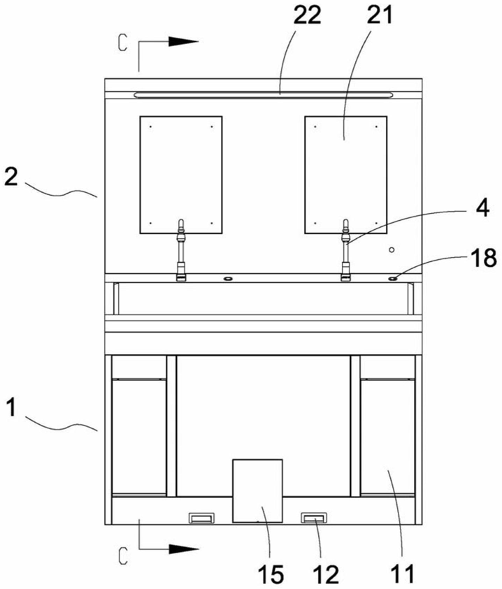 FIG. 1 — Front view of the knee-operated hand-washing basin
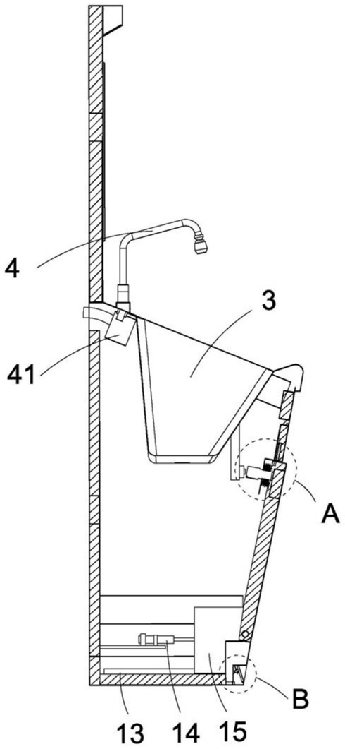 FIG. 2 — Cross-sectional view taken along plane C-C in FIG. 1
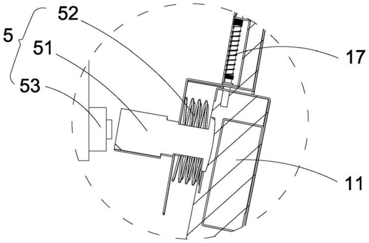 FIG. 3 — Enlarged view of part A in FIG. 2
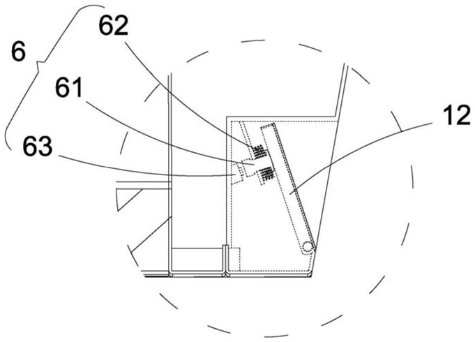 FIG. 4 — Enlarged view of part B in FIG. 2
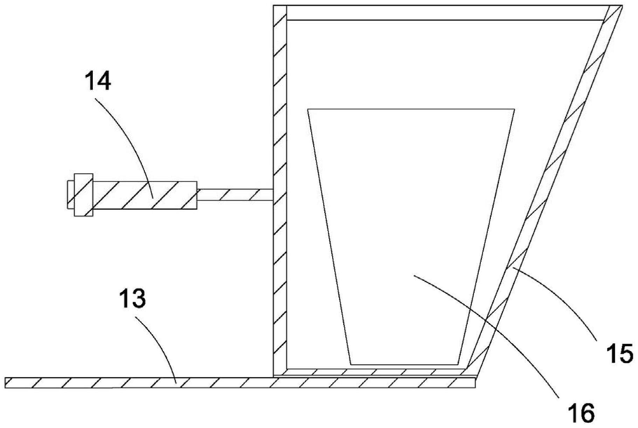 FIG. 5 — Structural schematic view of the guide rail, air cylinder, movable box and trash can