A Variable Air-Direction Air Supply Outlet (Utility Model CN 208504675 U)
The present utility model provides a variable air-direction air supply outlet, comprising a box body and a regulating valve, the regulating valve being fixedly connected at an air inlet of...
Abstract
The present utility model provides a variable air-direction air supply outlet, comprising a box body and a regulating valve, the regulating valve being fixedly connected at an air inlet of the box body. The box body comprises an inner cavity; an air outlet communicating with the inner cavity is defined through the bottom of the box body, and a filter is fixedly connected in the inner cavity at the air outlet. An arc-shaped diffuser shell is provided below the box body, the arc-shaped diffuser shell comprising an air collection cavity and an arc-shaped diffuser plate located at one side of the air collection cavity. An air collection port communicating with the air collection cavity is defined through the top of the arc-shaped diffuser shell, and the shape of the air collection port matches the shape of the bottom of the box body; the bottom of the box body is arranged on the air collection port. A lug A and a lug B are respectively provided on two opposite sides of the arc-shaped diffuser shell; the lug A is rotatably connected to one side wall of the box body; a motor is fixedly connected to one side of the inner cavity, and an output shaft of the motor is fixedly connected to the lug B. A plurality of air exhaust holes are equally spaced through the arc-shaped diffuser plate. The structure is simple and convenient to use; the air discharge area can be increased, the air discharge direction can be changed automatically, and the air change efficiency is improved.
Patent Information
| Item | Detail |
|---|---|
| Issuing authority | National Intellectual Property Administration of the People’s Republic of China (CNIPA) |
| Document type | Utility Model Patent |
| Authorization publication number | CN 208504675 U |
| Authorization publication date | 2019.02.15 |
| Application number | 201821017866.3 |
| Filing date | 2018.06.29 |
| Patentee | Dongguan Pengchi Purification Technology Co., Ltd. |
| Address | Tangyilangwei Road, Tangjiao Village, Chashan Town, Dongguan City, Guangdong Province 523378, China |
| Inventors | Wang Haiou; Hu Guopeng; Li Dexiong |
| Patent agency | Dongguan Yongqiao Intellectual Property Agency (General Partnership), Code 44400 |
| Patent agent | He Xinhua |
| International Patent Classification (IPC) | F24F 13/06 (2006.01); F24F 13/28 (2006.01) |
| Title of utility model | A Variable Air-Direction Air Supply Outlet |
Claims
-
A variable air-direction air supply outlet, comprising a box body (1) and a regulating valve (4), the regulating valve (4) being fixedly connected at an air inlet of the box body (1), characterized in that the box body (1) comprises an inner cavity (100);
- an air outlet (101) communicating with the inner cavity (100) is defined through the bottom of the box body (1), and a filter (3) is fixedly connected in the inner cavity (100) at the air outlet (101);
- an arc-shaped diffuser shell (5) is provided below the box body (1), the arc-shaped diffuser shell (5) comprising an air collection cavity (50) and an arc-shaped diffuser plate (51) located at one side of the air collection cavity (50);
- an air collection port (52) communicating with the air collection cavity (50) is defined through the top of the arc-shaped diffuser shell (5), the shape of the air collection port (52) matches the shape of the bottom of the box body (1), and the bottom of the box body (1) is arranged on the air collection port (52);
- a lug A (53) and a lug B (54) are respectively provided on two opposite sides of the arc-shaped diffuser shell (5), the lug A (53) is rotatably connected to one side wall of the box body (1), a motor (6) is fixedly connected to one side of the inner cavity (100), and an output shaft of the motor (6) is fixedly connected to the lug B (54);
- and a plurality of air exhaust holes (55) are equally spaced through the arc-shaped diffuser plate (51).
-
The variable air-direction air supply outlet according to claim 1, characterized in that the arc-shaped diffuser shell (5) further comprises air baffle plates (56) fixedly connected to two opposite sides of the arc-shaped diffuser plate (51), and arc-shaped receding portions (102) are provided on both opposite sides of the bottom of the box body (1).
-
The variable air-direction air supply outlet according to claim 1, characterized in that a silicone block (7) matching the shape of the inner cavity (100) is bonded in the inner cavity (100) at one side of the air outlet (101), a socket (70) matching the filter (3) is defined through a middle portion of the silicone block (7), and the filter (3) is arranged on the socket (70).
-
The variable air-direction air supply outlet according to claim 1, characterized in that a plurality of electric heating wires (8) are provided in the air collection cavity (50).
-
The variable air-direction air supply outlet according to claim 1, characterized in that the diameter of each air exhaust hole (55) is 5 mm.
Description
TECHNICAL FIELD
[0001] The present utility model relates to the technical field of air purification equipment, and in particular discloses a variable air-direction air supply outlet.
BACKGROUND ART
[0002] Air supply outlets are widely used in the prevention and control of indoor air pollution in various public places, and are widely used in the new construction and renovation of clean projects in the pharmaceutical, health, electronics, chemical and other industries; air filtered through the air supply outlets is delivered indoors, which effectively ensures that indoor air quality reaches an ideal state. An air supply outlet mainly consists of a box body, a diffuser plate, a filter, and a regulating valve, among which the diffuser plate functions to guide the discharge of air. In the air supply outlets on the market, the diffuser plate is fixedly installed below the box body; since a flat-plate diffuser plate is used, the air discharge area is small, resulting in low air change efficiency. In addition, the air discharge direction is fixed, and air can only be blown continuously in one direction, making it difficult to satisfy consumers' requirements for air blowing.
SUMMARY OF THE UTILITY MODEL
[0003] In view of this, it is necessary, in addressing the problems of the prior art, to provide a variable air-direction air supply outlet having a unique structure, which can increase the air discharge area, automatically change the air discharge direction, and improve the air change efficiency.
[0004] To solve the problems of the prior art, the present utility model discloses a variable air-direction air supply outlet, comprising a box body and a regulating valve, the regulating valve being fixedly connected at an air inlet of the box body; the box body comprises an inner cavity; an air outlet communicating with the inner cavity is defined through the bottom of the box body; a filter is fixedly connected in the inner cavity at the air outlet; an arc-shaped diffuser shell is provided below the box body, the arc-shaped diffuser shell comprising an air collection cavity and an arc-shaped diffuser plate located at one side of the air collection cavity; an air collection port communicating with the air collection cavity is defined through the top of the arc-shaped diffuser shell, the shape of the air collection port matching the shape of the bottom of the box body; the bottom of the box body is arranged on the air collection port; a lug A and a lug B are respectively provided on two opposite sides of the arc-shaped diffuser shell; the lug A is rotatably connected to one side wall of the box body; a motor is fixedly connected to one side of the inner cavity, and an output shaft of the motor is fixedly connected to the lug B; and a plurality of air exhaust holes are equally spaced through the arc-shaped diffuser plate.
[0005] Preferably, the arc-shaped diffuser shell further comprises air baffle plates fixedly connected to two opposite sides of the arc-shaped diffuser plate, and arc-shaped receding portions are provided on both opposite sides of the bottom of the box body.
[0006] Preferably, a silicone block matching the shape of the inner cavity is bonded in the inner cavity at one side of the air outlet, a socket matching the filter is defined through a middle portion of the silicone block, and the filter is arranged on the socket.
[0007] Preferably, a plurality of electric heating wires are provided in the air collection cavity.
[0008] Preferably, the diameter of each air exhaust hole is 5 mm.
[0009] The present utility model has the following beneficial effects: the present utility model discloses a variable air-direction air supply outlet having a unique structure; air passes through the regulating valve into the inner cavity and, after being filtered by the filter, enters the air collection cavity; a plurality of air exhaust holes are equally spaced through the arc-shaped diffuser plate, increasing the air discharge area. The motor drives the arc-shaped diffuser shell to swing back and forth around the box body, and the air flow in the air collection cavity is discharged through the air exhaust holes, forming a changing air direction. The structure is simple and convenient to use; the air discharge area can be increased, the air discharge direction can be changed automatically, and the air change efficiency improved. When the motor drives the arc-shaped diffuser shell to swing back and forth, the arc-shaped receding portions are provided to avoid blocking the movement of the air baffle plates, ensuring that the arc-shaped diffuser shell swings stably. The filter is fixed at the air outlet by the silicone block, improving the filtration sealing so as to prevent unfiltered air in the inner cavity from leaking out from the air outlet. The electric heating wires generate heat after being energized, and the air flow in the air collection cavity is heated by the electric heating wires and then discharged through the air exhaust holes, forming hot air.
BRIEF DESCRIPTION OF THE DRAWINGS
[0010] FIG. 1 is a schematic external structural view of the air supply outlet of the present utility model.
[0011] FIG. 2 is a schematic external structural view of the arc-shaped diffuser shell of the present utility model.
[0012] FIG. 3 is a schematic cross-sectional structural view of the air supply outlet of the present utility model.
[0013] The reference numerals are as follows: box body 1; inner cavity 100; air outlet 101; arc-shaped receding portion 102; filter 3; regulating valve 4; arc-shaped diffuser shell 5; air collection cavity 50; arc-shaped diffuser plate 51; air collection port 52; lug A 53; lug B 54; air exhaust hole 55; air baffle plate 56; motor 6; silicone block 7; socket 70; electric heating wire 8.
DETAILED DESCRIPTION OF EMBODIMENTS
[0014] To enable a further understanding of the features, technical means, and the specific objectives and functions achieved by the present utility model, the present utility model is described in further detail below in conjunction with the accompanying drawings and the detailed description of embodiments.
[0015] Reference is made to FIG. 1 through FIG. 3.
[0016] An embodiment of the present utility model discloses a variable air-direction air supply outlet, comprising a box body 1 and a regulating valve 4, the regulating valve 4 being fixedly connected at an air inlet of the box body 1; the box body 1 comprises an inner cavity 100; an air outlet 101 communicating with the inner cavity 100 is defined through the bottom of the box body 1; a filter 3 is fixedly connected in the inner cavity 100 at the air outlet 101; an arc-shaped diffuser shell 5 is provided below the box body 1, the arc-shaped diffuser shell 5 comprising an air collection cavity 50 and an arc-shaped diffuser plate 51 located at one side of the air collection cavity 50; an air collection port 52 communicating with the air collection cavity 50 is defined through the top of the arc-shaped diffuser shell 5, the shape of the air collection port 52 matches the shape of the bottom of the box body 1, and the bottom of the box body 1 is arranged on the air collection port 52; a lug A 53 and a lug B 54 are respectively provided on two opposite sides of the arc-shaped diffuser shell 5; the lug A 53 is rotatably connected to one side wall of the box body 1; a motor 6 is fixedly connected to one side of the inner cavity 100, and an output shaft of the motor 6 is fixedly connected to the lug B 54; and a plurality of air exhaust holes 55 are equally spaced through the arc-shaped diffuser plate 51.
[0017] In specific use, air passes through the regulating valve 4 into the inner cavity 100 and, after being filtered by the filter 3, enters the air collection cavity 50; a plurality of air exhaust holes 55 are equally spaced through the arc-shaped diffuser plate 51, increasing the air discharge area. The motor 6 drives the arc-shaped diffuser shell 5 to swing back and forth around the box body 1, and the air flow in the air collection cavity 50 is discharged through the air exhaust holes 55, forming a changing air direction. The structure is simple and convenient to use; the air discharge area can be increased, the air discharge direction can be changed automatically, and the air change efficiency improved.
[0018] Based on the above embodiment, the arc-shaped diffuser shell 5 further comprises air baffle plates 56 fixedly connected to two opposite sides of the arc-shaped diffuser plate 51, and arc-shaped receding portions 102 are provided on both opposite sides of the bottom of the box body 1. When the motor 6 drives the arc-shaped diffuser shell 5 to swing back and forth, the arc-shaped receding portions 102 are provided to avoid blocking the movement of the air baffle plates 56, ensuring that the arc-shaped diffuser shell 5 swings stably.
[0019] Based on the above embodiment, a silicone block 7 matching the shape of the inner cavity 100 is bonded in the inner cavity 100 at one side of the air outlet 101, a socket 70 matching the filter 3 is defined through a middle portion of the silicone block 7, and the filter 3 is arranged on the socket 70. The filter 3 is fixed at the air outlet 101 by the silicone block 7, and the elastic effect of the silicone block 7 can improve the filtration sealing, preventing air in the inner cavity 100 from leaking out from the air outlet 101 without being filtered by the filter 3.
[0020] Based on the above embodiment, a plurality of electric heating wires 8 are provided in the air collection cavity 50. The electric heating wires 8 generate heat after being energized, and the air flow in the air collection cavity 50 is heated by the electric heating wires 8 and then discharged through the air exhaust holes 55, whereby hot air can be formed.
[0021] To reduce the noise generated when the air flow passes through the air exhaust holes 55, based on the above embodiment, the diameter of each air exhaust hole 55 is 5 mm.
[0022] The above embodiments merely express one implementation of the present utility model, and the description thereof is relatively specific and detailed, but it should not be construed as limiting the patent scope of the present utility model. It should be noted that, for a person of ordinary skill in the art, various modifications and improvements may further be made without departing from the concept of the present utility model, and such modifications and improvements all fall within the protection scope of the present utility model. Therefore, the protection scope of the present utility model patent shall be subject to the appended claims.
Drawings
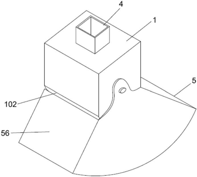 FIG. 1 — Schematic external structural view of the air supply outlet
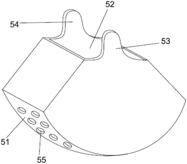 FIG. 2 — Schematic external structural view of the arc-shaped diffuser shell
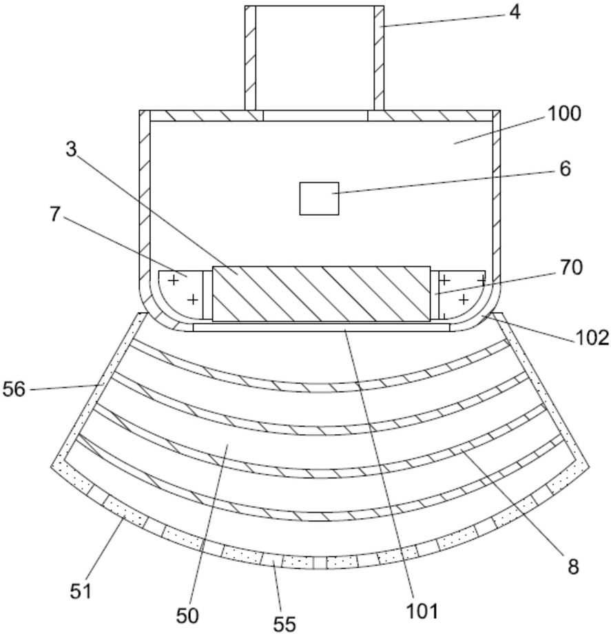 FIG. 3 — Schematic cross-sectional structural view of the air supply outlet