A Door Frame Structure (Utility Model CN 210564042 U)
The present utility model provides a door frame structure. A vertical frame strip A and a vertical frame strip B each comprise a vertical U-shaped strip plate, a vertical profiled strip...
Abstract
The present utility model provides a door frame structure. A vertical frame strip A and a vertical frame strip B each comprise a vertical U-shaped strip plate, a vertical profiled strip plate, and a plurality of spacers A. The vertical U-shaped strip plate and the vertical profiled strip plate are correspondingly fitted together so as to form a reserved groove. The spacers A are correspondingly arranged in sequence in an array along a length direction of the reserved groove, and the vertical U-shaped strip plate, the vertical profiled strip plate, and the plurality of spacers A form a mounting groove. A horizontal frame strip comprises a horizontal U-shaped strip plate, a horizontal profiled strip plate, and a plurality of spacers B. The horizontal U-shaped strip plate and the horizontal profiled strip plate are correspondingly fitted together so as to form a reserved groove, and the spacers B are correspondingly arranged in sequence in an array along the length direction of the reserved groove. A surface of one side of the vertical profiled strip plate along its length direction facing the horizontal profiled strip plate is provided with a plurality of insertion holes, and both ends of the horizontal profiled strip plate are provided with insertion hooks cooperating with the insertion holes. The connecting structure of the frame strips is adjusted to facilitate assembly and disassembly, thereby saving adjustment time.
Patent Information
| Item | Detail |
|---|---|
| Issuing authority | National Intellectual Property Administration of the People’s Republic of China (CNIPA) |
| Document type | Utility Model Patent |
| Authorization publication number | CN 210564042 U |
| Authorization publication date | 2020-05-19 |
| Application number | 201920807158.8 |
| Filing date | 2019-05-31 |
| Patentee | Dongguan Pengchi Purification Technology Co., Ltd. |
| Address | Tangyilangwei Road, Tangjiao Village, Chashan Town, Dongguan City, Guangdong Province 523378, China |
| Inventors | Wang Haiou; Hu Guopeng; Li Dexiong |
| Patent agency | Dongguan Yongqiao Intellectual Property Agency (General Partnership) 44400 |
| Patent agent | He Xinhua |
| International Patent Classification (IPC) | E06B 1/52(2006.01) |
| Title of utility model | A Door Frame Structure |
Claims
-
A door frame structure, comprising a vertical frame strip A (22), a vertical frame strip B (23), and a horizontal frame strip (11), characterized in that:
- the vertical frame strip A (22) and the vertical frame strip B (23) are disposed parallel to each other;
- the horizontal frame strip (11) is connected between the vertical frame strip A (22) and the vertical frame strip B (23);
- the vertical frame strip A (22) and the vertical frame strip B (23) have the same structure;
- the vertical frame strip A (22) and the vertical frame strip B (23) each comprise a vertical U-shaped strip plate (12), a vertical profiled strip plate (29), and a plurality of spacers A (13);
- the vertical U-shaped strip plate (12) and the vertical profiled strip plate (29) are correspondingly fitted together so as to form a reserved groove (10);
- the spacers A (13) are correspondingly arranged in sequence in an array along a length direction of the reserved groove (10);
- the vertical U-shaped strip plate (12), the vertical profiled strip plate (29), and the plurality of spacers A (13) form a mounting groove;
- the horizontal frame strip (11) comprises a horizontal U-shaped strip plate (15), a horizontal profiled strip plate (21), and a plurality of spacers B (28);
- the horizontal U-shaped strip plate (15) and the horizontal profiled strip plate (21) are correspondingly fitted together so as to form a reserved groove (10);
- the spacers B (28) are correspondingly arranged in sequence in an array along the length direction of the reserved groove (10);
- a surface of one side of the vertical profiled strip plate (29) along its length direction facing the horizontal profiled strip plate (21) is provided with a plurality of insertion holes (14);
- both ends of the horizontal profiled strip plate (21) are provided with insertion hooks (17) cooperating with the insertion holes (14); and
- the insertion hooks (17) are correspondingly inserted into the insertion holes (14) to connect the vertical frame strip A (22), the horizontal frame strip (11), and the vertical frame strip B (23) into a door frame structure.
-
The door frame structure according to claim 1, characterized in that the insertion holes (14) are configured as flared insertion holes (14) that are wide at one end and narrow at the other end, and the insertion hooks (17) are configured in an arrowhead shape.
-
The door frame structure according to claim 2, characterized in that the horizontal profiled strip plate (21) comprises a first L-shaped bent section (18), a second L-shaped bent section (20), and a connecting section A (19), the first L-shaped bent section (18) being connected to the second L-shaped bent section (20) through the connecting section A (19), and the insertion hooks (17) being correspondingly disposed on two side surfaces of the connecting section A (19).
-
The door frame structure according to claim 3, characterized in that the vertical profiled strip plate (29) comprises a third L-shaped bent section (30), a fourth L-shaped bent section (25), and a connecting section B (24), the third L-shaped bent section (30) being connected to the fourth L-shaped bent section (25) through the connecting section B (24).
-
The door frame structure according to claim 4, characterized in that each spacer A (13) comprises a U-shaped section (26), a T-shaped extension section (27) disposed on one side of the U-shaped section (26), and an L-shaped extension section (16) disposed on the other side of the U-shaped section (26), the U-shaped section (26), the T-shaped extension section (27), and the L-shaped extension section (16) being an integrally formed structure.
Description
TECHNICAL FIELD
[0001] The present utility model relates to the technical field of door frame processing, and in particular to an improved door frame structure.
BACKGROUND ART
[0002] In the prior art, a combined door frame is generally installed in such a manner that the door frame is assembled first, the frame strips on each side of the door frame are fixed by welding or threaded connection, and the door frame is then installed after the wall is constructed. A frequent problem with this assembly method is that after the door frame is fixed, the door is prone to failing to be installed, which requires complete disassembly and reconnection, consuming time and effort and seriously affecting the progress of the project. This situation urgently needs to be solved.
SUMMARY OF THE UTILITY MODEL
[0003] Based on the above, an object of the present utility model is to provide a door frame structure, in which the connecting structure of the frame strips is adjusted to facilitate assembly and disassembly, thereby saving adjustment time.
[0004] The present utility model provides a door frame structure, comprising a vertical frame strip A, a vertical frame strip B, and a horizontal frame strip. The vertical frame strip A and the vertical frame strip B are disposed parallel to each other, and the horizontal frame strip is connected between the vertical frame strip A and the vertical frame strip B. The vertical frame strip A and the vertical frame strip B have the same structure. The vertical frame strip A and the vertical frame strip B each comprise a vertical U-shaped strip plate, a vertical profiled strip plate, and a plurality of spacers A. The vertical U-shaped strip plate and the vertical profiled strip plate are correspondingly fitted together so as to form a reserved groove. The spacers A are correspondingly arranged in sequence in an array along the length direction of the reserved groove, and the vertical U-shaped strip plate, the vertical profiled strip plate, and the plurality of spacers A form a mounting groove. The horizontal frame strip comprises a horizontal U-shaped strip plate, a horizontal profiled strip plate, and a plurality of spacers B. The horizontal U-shaped strip plate and the horizontal profiled strip plate are correspondingly fitted together so as to form a reserved groove, and the spacers B are correspondingly arranged in sequence in an array along the length direction of the reserved groove. A surface of one side of the vertical profiled strip plate along its length direction facing the horizontal profiled strip plate is provided with a plurality of insertion holes, and both ends of the horizontal profiled strip plate are provided with insertion hooks cooperating with the insertion holes. The insertion hooks are correspondingly inserted into the insertion holes to connect the vertical frame strip A, the horizontal frame strip, and the vertical frame strip B into a door frame structure.
[0005] As a preferred solution, the insertion holes are configured as flared insertion holes that are wide at one end and narrow at the other end, and the insertion hooks are configured in an arrowhead shape.
[0006] As a preferred solution, the horizontal profiled strip plate comprises a first L-shaped bent section, a second L-shaped bent section, and a connecting section A. The first L-shaped bent section is connected to the second L-shaped bent section through the connecting section A, and the insertion hooks are correspondingly disposed on two side surfaces of the connecting section A.
[0007] As a preferred solution, the vertical profiled strip plate comprises a third L-shaped bent section, a fourth L-shaped bent section, and a connecting section B. The third L-shaped bent section is connected to the fourth L-shaped bent section through the connecting section B.
[0008] As a preferred solution, each spacer A comprises a U-shaped section, a T-shaped extension section disposed on one side of the U-shaped section, and an L-shaped extension section disposed on the other side of the U-shaped section. The U-shaped section, the T-shaped extension section, and the L-shaped extension section are an integrally formed structure.
[0009] The present utility model has the following beneficial effects: the surface of one side of the vertical profiled strip plate along its length direction facing the horizontal profiled strip plate is provided with a plurality of insertion holes; both ends of the horizontal profiled strip plate are provided with insertion hooks cooperating with the insertion holes; and the insertion hooks are correspondingly inserted into the insertion holes to connect the vertical frame strip A, the horizontal frame strip, and the vertical frame strip B into a door frame structure. With this structural approach, the vertical frame strip A, the horizontal frame strip, and the vertical frame strip B can be easily disassembled and assembled, effectively solving the installation difficulty caused by the door being mounted last during assembly. With the door frame of the present structure, there is no need to disassemble the entire door frame and then assemble it together with the door; it is only necessary to disengage the insertion hooks of the vertical frame strip A or the vertical frame strip B and then correspondingly adjust the installation position, which is convenient and fast.
BRIEF DESCRIPTION OF THE DRAWINGS
[0010] FIG. 1 is a schematic structural view of the prior art.
[0011] FIG. 2 is a schematic exploded structural view of the present utility model.
[0012] FIG. 3 is a schematic perspective structural view of the present utility model from another angle.
[0013] FIG. 4 is a side view of the present utility model.
[0014] FIG. 5 is an enlarged view of position A in FIG. 4.
[0015] The reference numerals are as follows: reserved groove (10), horizontal frame strip (11), vertical U-shaped strip plate (12), spacer A (13), insertion hole (14), horizontal U-shaped strip plate (15), L-shaped extension section (16), insertion hook (17), first L-shaped bent section (18), second L-shaped bent section (20), connecting section A (19), horizontal profiled strip plate (21), vertical frame strip A (22), vertical frame strip B (23), fourth L-shaped bent section (25), connecting section B (24), U-shaped section (26), T-shaped extension section (27), spacer B (28), vertical profiled strip plate (29), and third L-shaped bent section (30).
DETAILED DESCRIPTION OF EMBODIMENTS
[0016] In order to further understand the features, technical means, and specific objects and functions achieved by the present utility model, the present utility model is described in further detail below with reference to the accompanying drawings and specific embodiments.
[0017] Referring to FIGS. 1-5, a door frame structure comprises a vertical frame strip A (22), a vertical frame strip B (23), and a horizontal frame strip (11). The vertical frame strip A (22) and the vertical frame strip B (23) are disposed parallel to each other, and the horizontal frame strip (11) is connected between the vertical frame strip A (22) and the vertical frame strip B (23). The vertical frame strip A (22) and the vertical frame strip B (23) have the same structure. The vertical frame strip A (22) and the vertical frame strip B (23) each comprise a vertical U-shaped strip plate (12), a vertical profiled strip plate (29), and a plurality of spacers A (13). In this embodiment, two spacers A (13) are provided. The vertical U-shaped strip plate (12) and the vertical profiled strip plate (29) are correspondingly fitted together so as to form a reserved groove (10). The spacers A (13) are correspondingly arranged in sequence in an array along the length direction of the reserved groove (10). The vertical U-shaped strip plate (12), the vertical profiled strip plate (29), and the plurality of spacers A (13) form a mounting groove for installation with a wall. The horizontal frame strip (11) comprises a horizontal U-shaped strip plate (15), a horizontal profiled strip plate (21), and a plurality of spacers B (28). The spacer A (13) and the spacer B (28) have the same structure. In this embodiment, two spacers B (28) are provided. The horizontal U-shaped strip plate (15) and the horizontal profiled strip plate (21) are correspondingly fitted together so as to form a reserved groove (10). The spacers B (28) are correspondingly arranged in sequence in an array along the length direction of the reserved groove (10). A surface of one side of the vertical profiled strip plate (29) along its length direction facing the horizontal profiled strip plate (21) is provided with a plurality of insertion holes (14). In this embodiment, two insertion holes (14) are provided side by side. Both ends of the horizontal profiled strip plate (21) are provided with insertion hooks (17) cooperating with the insertion holes (14), and the insertion hooks (17) are correspondingly inserted into the insertion holes (14) to connect the vertical frame strip A (22), the horizontal frame strip (11), and the vertical frame strip B (23) into a door frame structure. The spacers A (13) and the spacers B (28) serve as reinforcing ribs on the one hand, and fix the shape of the mounting groove on the other hand, so as to interface well with the wall.
[0018] The insertion holes (14) are configured as flared insertion holes (14) that are wide at one end and narrow at the other end, and the insertion hooks (17) are configured in an arrowhead shape. The insertion hook (17) is inserted from the wide side of the insertion hole (14) and then moved to the narrow side to achieve locking.
[0019] The horizontal profiled strip plate (21) comprises a first L-shaped bent section (18), a second L-shaped bent section (20), and a connecting section A (19). The first L-shaped bent section (18) is connected to the second L-shaped bent section (20) through the connecting section A (19), and the insertion hooks (17) are correspondingly disposed on two side surfaces of the connecting section A (19).
[0020] The vertical profiled strip plate (29) comprises a third L-shaped bent section (30), a fourth L-shaped bent section (25), and a connecting section B (24). The third L-shaped bent section (30) is connected to the fourth L-shaped bent section (25) through the connecting section B (24).
[0021] Each spacer A (13) comprises a U-shaped section (26), a T-shaped extension section (27) disposed on one side of the U-shaped section (26), and an L-shaped extension section (16) disposed on the other side of the U-shaped section (26). The U-shaped section (26), the T-shaped extension section (27), and the L-shaped extension section (16) are an integrally formed structure.
[0022] In an assembled state, the third L-shaped bent section (30) is in close contact with one side of the vertical U-shaped strip plate (12); the T-shaped extension section (27) of each spacer A (13) is in close contact with the interior of the vertical U-shaped strip plate (12); the L-shaped extension section (16) of each spacer A (13) is in close contact with the fourth L-shaped bent section (25); the T-shaped extension section of each spacer B (28) is in close contact with the interior of the horizontal U-shaped strip plate (15); and the L-shaped extension section of each spacer B (28) is in close contact with the second L-shaped bent section (20).
[0023] In this embodiment, the surface of one side of the vertical profiled strip plate along its length direction facing the horizontal profiled strip plate is provided with a plurality of insertion holes; both ends of the horizontal profiled strip plate are provided with insertion hooks cooperating with the insertion holes; and the insertion hooks are correspondingly inserted into the insertion holes to connect the vertical frame strip A, the horizontal frame strip, and the vertical frame strip B into a door frame structure. With this structural approach, the vertical frame strip A, the horizontal frame strip, and the vertical frame strip B can be easily disassembled and assembled, effectively solving the installation difficulty caused by the door being mounted last during assembly. With the door frame of the present structure, there is no need to disassemble the entire door frame and then assemble it together with the door; it is only necessary to disengage the insertion hooks of the vertical frame strip A or the vertical frame strip B and then correspondingly adjust the installation position, which is convenient and fast.
[0024] The above embodiments only describe one embodiment of the present utility model, and the description thereof is relatively specific and detailed. However, this should not be construed as a limitation on the patent scope of the present utility model. It should be noted that, for a person of ordinary skill in the art, without departing from the concept of the present utility model, several modifications and improvements can be made, all of which fall within the protection scope of the present utility model. Therefore, the protection scope of the present utility model patent shall be defined by the appended claims.
Drawings
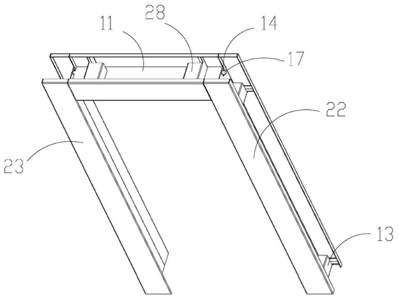 FIG. 1 — Schematic structural view of the prior art
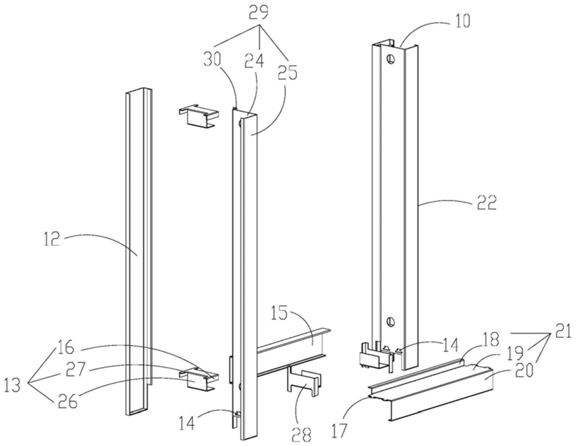 FIG. 2 — Schematic exploded structural view of the present utility model
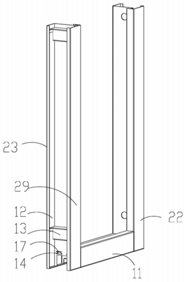 FIG. 3 — Schematic perspective structural view from another angle
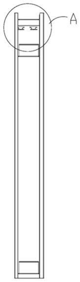 FIG. 4 — Side view of the present utility model
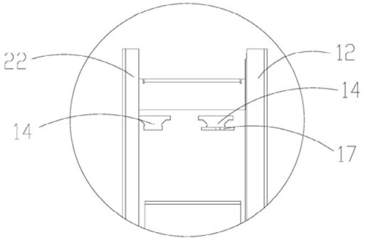 FIG. 5 — Enlarged view of position A in FIG. 4