A Medical Writing Desk (Utility Model CN 210768321 U)
The present utility model provides a medical writing desk, comprising a cabinet body and a cabinet door. A light source is provided at an upper end inside the cabinet body, and a drive...
Abstract
The present utility model provides a medical writing desk, comprising a cabinet body and a cabinet door. A light source is provided at an upper end inside the cabinet body, and a drive assembly and a driven assembly are respectively provided on two sides inside the cabinet body. The drive assembly comprises a gear motor, a drive rod and a first connecting rod, and a lower end of the first connecting rod is connected to the cabinet door. The driven assembly comprises a bearing, a rocking rod and a second connecting rod, and a lower end of the second connecting rod is connected to the cabinet door. A motor switch electrically connected to the gear motor is provided on the left side of a front end of the cabinet body, a light source switch electrically connected to the light source is provided on an upper side of the front end of the cabinet body, and an infrared sensor is further provided on the upper side of the front end of the cabinet body. In the medical writing desk of the present utility model, the cabinet door is driven by the gear motor, realizing intelligent opening and closing.
Patent Information
| Item | Detail |
|---|---|
| Issuing authority | National Intellectual Property Administration of the People’s Republic of China (CNIPA) |
| Document type | Utility Model Patent |
| Authorization publication number | CN 210768321 U |
| Authorization publication date | June 16, 2020 |
| Application number | 201920992505.9 |
| Filing date | June 28, 2019 |
| Patentee | Dongguan Pengchi Purification Technology Co., Ltd. |
| Address | Tangyilangwei Road, Tangjiao Village, Chashan Town, Dongguan City, Guangdong Province 523378, China |
| Inventors | Hu Guopeng |
| Patent agency | Dongguan Yongqiao Intellectual Property Agency (General Partnership) 44400 |
| Patent agent | He Xinhua |
| International Patent Classification (IPC) | E05F 15/616 (2015.01); E05F 15/43 (2015.01); E06B 3/38 (2006.01); E06B 7/28 (2006.01); A47B 81/00 (2006.01); A47B 46/00 (2006.01) |
| Title of utility model | A Medical Writing Desk |
Claims
-
A medical writing desk, comprising a cabinet body (1) and a cabinet door (2), a light source (3) being provided at an upper end inside the cabinet body (1), characterized in that a drive assembly (4) and a driven assembly (5) are respectively provided on two sides inside the cabinet body (1);
- the drive assembly (4) comprises a gear motor (41) fixed to one side of the cabinet body (1), a drive rod (42) connected to an output shaft of the gear motor (41), and a first connecting rod (43) rotationally connected to a lower end of the drive rod (42), and a lower end of the first connecting rod (43) is connected to the cabinet door (2);
- the driven assembly (5) comprises a bearing (51) fixed to an inner side of the cabinet body (1), a rocking rod (52) rotationally connected to the bearing (51), and a second connecting rod (53) rotationally connected to a lower end of the rocking rod (52), and a lower end of the second connecting rod (53) is connected to the cabinet door (2);
- a motor switch (11) electrically connected to the gear motor (41) is provided on the left side of a front end of the cabinet body (1), a light source switch (12) electrically connected to the light source (3) is provided on an upper side of the front end of the cabinet body (1), and an infrared sensor (13) is further provided on the upper side of the front end of the cabinet body (1).
-
The medical writing desk according to claim 1, characterized in that a spring latch (6) is further connected to the bottom of the first connecting rod (43), and the other end of the spring latch (6) is connected to an inner side of the cabinet body (1).
-
The medical writing desk according to claim 1, characterized in that a control box (7) is provided in the cabinet body (1), and the motor switch (11), the light source switch (12) and the infrared sensor (13) are all electrically connected to the control box (7).
-
The medical writing desk according to claim 3, characterized in that a display screen (8) is further provided on an outer side of the cabinet door (2), and the display screen (8) is electrically connected to the control box (7).
-
The medical writing desk according to claim 1, characterized in that a dust cover (9) is further sleeved on an outer side of the gear motor (41).
Description
TECHNICAL FIELD
[0001] The present utility model relates to the field of medical equipment, and in particular to a medical writing desk.
BACKGROUND ART
[0002] The medical writing desk is a piece of equipment commonly used in hospital operating rooms. When opened, the cabinet door forms a large flat surface together with a bottom face of the cabinet body, on which nurses or doctors can write; when not in use, the door is closed to form an integral structure with the wall. At present, the cabinet door of a medical writing desk is opened and closed by means of a handle on the door through manual force, and is then fixed by a power-assist hinge. Such a door is very laborious to open and close. Since the door is opened outward and turned downward by 90 degrees, the power-assist hinge has to overcome two contradictory forces, namely strong pulling and strong pressing, and is thus also prone to breakage; in addition, the door handle also has disinfection dead corners during disinfection, where harmful bacteria easily lurk.
SUMMARY OF THE UTILITY MODEL
[0003] In view of the above problems, the present utility model provides a medical writing desk in which the cabinet door is driven by a gear motor, realizing intelligent opening and closing.
[0004] To achieve the above object, the present utility model solves the above problem through the following technical solutions:
[0005] A medical writing desk comprises a cabinet body and a cabinet door. A light source is provided at an upper end inside the cabinet body, characterized in that a drive assembly and a driven assembly are respectively provided on two sides inside the cabinet body. The drive assembly comprises a gear motor fixed to one side of the cabinet body, a drive rod connected to an output shaft of the gear motor, and a first connecting rod rotationally connected to a lower end of the drive rod, and a lower end of the first connecting rod is connected to the cabinet door. The driven assembly comprises a bearing fixed to an inner side of the cabinet body, a rocking rod rotationally connected to the bearing, and a second connecting rod rotationally connected to a lower end of the rocking rod, and a lower end of the second connecting rod is connected to the cabinet door. A motor switch electrically connected to the gear motor is provided on the left side of a front end of the cabinet body, a light source switch electrically connected to the light source is provided on an upper side of the front end of the cabinet body, and an infrared sensor is further provided on the upper side of the front end of the cabinet body.
[0006] Specifically, a spring latch is further connected to the bottom of the first connecting rod, and the other end of the spring latch is connected to an inner side of the cabinet body.
[0007] Specifically, a control box is provided in the cabinet body, and the motor switch, the light source switch and the infrared sensor are all electrically connected to the control box.
[0008] Specifically, a display screen is further provided on an outer side of the cabinet door, and the display screen is electrically connected to the control box.
[0009] Specifically, a dust cover is further sleeved on an outer side of the gear motor.
[0010] The beneficial effects of the present utility model are as follows:
[0011] First, in the medical writing desk provided by the present utility model, the cabinet door is driven by the gear motor, realizing intelligent opening and closing. An infrared sensor is added on the upper side of the front end of the cabinet body, and the infrared sensor can detect the front side of the cabinet body, preventing hands from being pinched when the cabinet door is closed;
[0012] Second, a display screen is added, by which information such as time, temperature and humidity can be displayed. Moreover, the display screen is arranged on the cabinet door, so that the space at the cabinet door position is reasonably utilized, avoiding occupation of other space in the operating room due to separate installation of a display screen.
BRIEF DESCRIPTION OF THE DRAWINGS
[0013] FIG. 1 is structural schematic view I of a medical writing desk according to the present utility model.
[0014] FIG. 2 is structural schematic view II of a medical writing desk according to the present utility model.
[0015] FIG. 3 is structural schematic view III of a medical writing desk according to the present utility model.
[0016] FIG. 4 is a cross-sectional view of the gear motor and the drive rod in the present utility model.
[0017] The reference numerals are as follows: cabinet body 1; motor switch 11; light source switch 12; infrared sensor 13; cabinet door 2; light source 3; drive assembly 4; gear motor 41; drive rod 42; first connecting rod 43; driven assembly 5; bearing 51; rocking rod 52; second connecting rod 53; spring latch 6; control box 7; display screen 8; dust cover 9.
DETAILED DESCRIPTION OF EMBODIMENTS
[0018] The present utility model will be described in further detail below in conjunction with the embodiments and the accompanying drawings, but the embodiments of the present utility model are not limited thereto.
[0019] As shown in FIGS. 1-4:
[0020] A medical writing desk comprises a cabinet body 1 and a cabinet door 2. A light source 3 is provided at an upper end inside the cabinet body 1, characterized in that a drive assembly 4 and a driven assembly 5 are respectively provided on two sides inside the cabinet body 1. The drive assembly 4 comprises a gear motor 41 fixed to one side of the cabinet body 1, a drive rod 42 connected to an output shaft of the gear motor 41, and a first connecting rod 43 rotationally connected to a lower end of the drive rod 42, and a lower end of the first connecting rod 43 is connected to the cabinet door 2. When the cabinet door is opened, the gear motor 41 rotates to drive the drive rod 42 to rotate, and the drive rod 42 pushes the first connecting rod 43 until the drive rod 42 and the first connecting rod 43 are arranged in a straight line, at which time the cabinet door 2 forms an angle of 90 degrees with the cabinet body. When the cabinet door is closed, the gear motor 41 rotates to drive the drive rod 42 to rotate, and the drive rod 42 pulls the first connecting rod 43 until the cabinet door 2 is in close contact with the cabinet body 1. The driven assembly 5 comprises a bearing 51 fixed to an inner side of the cabinet body 1, a rocking rod 52 rotationally connected to the bearing 51, and a second connecting rod 53 rotationally connected to a lower end of the rocking rod 52, and a lower end of the second connecting rod 53 is connected to the cabinet door 2. A motor switch 11 electrically connected to the gear motor 41 is provided on the left side of a front end of the cabinet body 1, and the start or stop of the gear motor 41 is controlled by the motor switch 11, thereby controlling the opening and closing of the cabinet door 2. A light source switch 12 electrically connected to the light source 3 is provided on an upper side of the front end of the cabinet body 1, and an infrared sensor 13 is further provided on the upper side of the front end of the cabinet body 1. During a door-closing operation, the infrared sensor 13 continuously emits infrared rays and can detect the position at the front side of the cabinet body 1, thereby preventing hands from being pinched when the cabinet door 2 is closed.
[0021] Preferably, a spring latch 6 is further connected to the bottom of the first connecting rod 43, and the other end of the spring latch 6 is connected to an inner side of the cabinet body 1. Under the action of spring force, the spring latch 6 enables a pin head of the first connecting rod 43 to automatically return and self-lock.
[0022] Preferably, a control box 7 is provided in the cabinet body 1, and the motor switch 11, the light source switch 12 and the infrared sensor 13 are all electrically connected to the control box 7.
[0023] Preferably, a display screen 8 is further provided on an outer side of the cabinet door 2, and the display screen 8 is electrically connected to the control box 7.
[0024] Preferably, a dust cover 9 is further sleeved on an outer side of the gear motor 41.
[0025] The above embodiments only illustrate one embodiment of the present utility model, and the description thereof is relatively specific and detailed, but it should not be construed as limiting the patent scope of the present utility model. It should be noted that those of ordinary skill in the art may make various modifications and improvements without departing from the concept of the present utility model, and these all fall within the protection scope of the present utility model. Therefore, the patent protection scope of the present utility model shall be subject to the appended claims.
Drawings
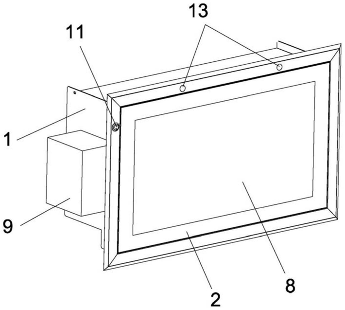 FIG. 1 — Structural schematic view I of the medical writing desk
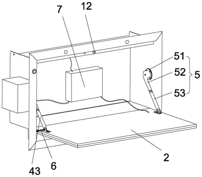 FIG. 2 — Structural schematic view II of the medical writing desk
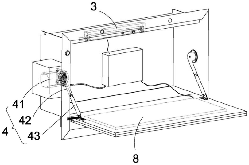 FIG. 3 — Structural schematic view III of the medical writing desk
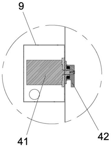 FIG. 4 — Cross-sectional view of the gear motor and the drive rod