An Observation Window Structure (Utility Model CN 210564146 U)
The present utility model provides an observation window structure. An observation window comprises a fixing structure, a glass body A, and a glass body B. The fixing structure comprises a...
Abstract
The present utility model provides an observation window structure. An observation window comprises a fixing structure, a glass body A, and a glass body B. The fixing structure comprises a vertical bar body A, a vertical bar body B, a horizontal bar body A, and a horizontal bar body B. The vertical bar body A, the vertical bar body B, the horizontal bar body A, and the horizontal bar body B are each composed of a first U-shaped plate body and a second U-shaped plate body. The second U-shaped plate body is centrally and fixedly disposed on the first U-shaped plate body. A width of the first U-shaped plate body is greater than a width of the second U-shaped plate body, so as to form stepped positions on two sides of the second U-shaped plate body. A sunken position is disposed on one side surface of each of the glass body A and the glass body B. The stepped positions on the same side of the vertical bar body A, the vertical bar body B, the horizontal bar body A, and the horizontal bar body B enclose a glass placement space. The sides of the glass body A and the glass body B having the sunken positions are correspondingly disposed in the glass placement spaces, respectively. By providing the fixing structure and cooperating with the adjustment of the glass body structure, the sealing performance of the observation window is improved.
Patent Information
| Item | Detail |
|---|---|
| Issuing authority | National Intellectual Property Administration of the People’s Republic of China (CNIPA) |
| Document type | Utility Model Patent |
| Authorization publication number | CN 210564146 U |
| Authorization publication date | 2020-05-19 |
| Application number | 201920807159.2 |
| Filing date | 2019-05-31 |
| Patentee | Dongguan Pengchi Purification Technology Co., Ltd. |
| Address | Tangyilangwei Road, Tangjiao Village, Chashan Town, Dongguan City, Guangdong Province 523378, China |
| Inventors | Wang Haiou; Hu Guopeng; Li Dexiong |
| Patent agency | Dongguan Yongqiao Intellectual Property Agency (General Partnership) 44400 |
| Patent agent | He Xinhua |
| International Patent Classification (IPC) | E06B 3/58(2006.01) |
| Title of utility model | An Observation Window Structure |
Claims
-
An observation window structure, comprising a metal plate body A (13) and a metal plate body B (10), characterized in that:
- the metal plate body A (13) and the metal plate body B (10) each correspondingly define a mounting hole at a reserved hole position (15);
- an observation window is correspondingly disposed at the position of the mounting hole;
- the observation window comprises a fixing structure (12), a glass body A (16), and a glass body B (11);
- the fixing structure (12) comprises a vertical bar body A (19), a vertical bar body B (14), a horizontal bar body A (17), and a horizontal bar body B (18);
- the vertical bar body A (19) and the vertical bar body B (14) are disposed parallel to each other, and the horizontal bar body A (17) and the horizontal bar body B (18) are disposed parallel to each other;
- the horizontal bar body A (17) and the horizontal bar body B (18) are respectively disposed between the vertical bar body A (19) and the vertical bar body B (14), and are respectively connected to both ends of the vertical bar body A (19) and the vertical bar body B (14);
- the vertical bar body A (19), the vertical bar body B (14), the horizontal bar body A (17), and the horizontal bar body B (18) are each composed of a first U-shaped plate body (25) and a second U-shaped plate body (24);
- the second U-shaped plate body (24) is centrally and fixedly disposed on the first U-shaped plate body (25);
- the width of the first U-shaped plate body (25) is greater than the width of the second U-shaped plate body (24), so as to form stepped positions (21) on two sides of the second U-shaped plate body (24);
- a position adjacent to an edge on one side surface of each of the glass body A (16) and the glass body B (11) is provided with a sunken position (20);
- the stepped positions (21) on the same side of the vertical bar body A (19), the vertical bar body B (14), the horizontal bar body A (17), and the horizontal bar body B (18) enclose a glass placement space;
- the sides of the glass body A (16) and the glass body B (11) having the sunken positions (20) are correspondingly disposed in the glass placement spaces, respectively; and
- an adhesive layer for adhesively fixing the glass body A (16) and the glass body B (11), respectively, is disposed in each glass placement space.
-
The observation window structure according to claim 1, characterized in that the shape of each sunken position (20) is respectively identical to the shape of the glass body A (16) and the shape of the glass body B (11).
-
The observation window structure according to claim 2, characterized in that a depth of each sunken position (20) is set to 0.1-0.2 cm.
-
The observation window structure according to claim 3, characterized in that an extension surface (23) is formed on a side of each second U-shaped plate body (24) away from the corresponding first U-shaped plate body (25) and in a direction toward the stepped position (21), and each extension surface (23) is in close contact with the sunken position (20) at that position.
-
The observation window structure according to any one of claims 1-4, characterized in that a strip-shaped reinforcing rib (26) is disposed inside each second U-shaped plate body (24).
-
The observation window structure according to any one of claims 1-4, characterized in that each corner of the glass body A (16) is provided with a chamfer (27), and each corner of the glass body B (11) is provided with a chamfer (27).
Description
TECHNICAL FIELD
[0001] The present utility model relates to the technical field of observation window processing, and in particular to an improved observation window structure.
BACKGROUND ART
[0002] An observation window is a window used for observing the test condition of a sample in a working space. In the prior art, an observation window is generally structured such that a metal plate is attached to a side edge of glass and then fixed with glue. With such a structural arrangement, the sealing performance is not good enough, so it is not suitable for environments with high cleanliness requirements. In view of this situation, the structure of the observation window urgently needs to be improved.
SUMMARY OF THE UTILITY MODEL
[0003] Based on the above, an object of the present utility model is to provide an observation window structure, in which the sealing performance of the observation window is improved by providing the fixing structure and cooperating with the adjustment of the glass body structure.
[0004] The present utility model provides an observation window structure, comprising a metal plate body A and a metal plate body B. The metal plate body A and the metal plate body B each correspondingly define a mounting hole at a reserved hole position, and an observation window is correspondingly disposed at the position of the mounting hole. The observation window comprises a fixing structure, a glass body A, and a glass body B. The fixing structure comprises a vertical bar body A, a vertical bar body B, a horizontal bar body A, and a horizontal bar body B. The vertical bar body A and the vertical bar body B are disposed parallel to each other, and the horizontal bar body A and the horizontal bar body B are disposed parallel to each other. The horizontal bar body A and the horizontal bar body B are respectively disposed between the vertical bar body A and the vertical bar body B, and are respectively connected to both ends of the vertical bar body A and the vertical bar body B. The vertical bar body A, the vertical bar body B, the horizontal bar body A, and the horizontal bar body B are each composed of a first U-shaped plate body and a second U-shaped plate body. The second U-shaped plate body is centrally and fixedly disposed on the first U-shaped plate body. The width of the first U-shaped plate body is greater than the width of the second U-shaped plate body, so as to form stepped positions on two sides of the second U-shaped plate body. A position adjacent to an edge on one side surface of each of the glass body A and the glass body B is provided with a sunken position. The stepped positions on the same side of the vertical bar body A, the vertical bar body B, the horizontal bar body A, and the horizontal bar body B enclose a glass placement space. The sides of the glass body A and the glass body B having the sunken positions are correspondingly disposed in the glass placement spaces, respectively. An adhesive layer for adhesively fixing the glass body A and the glass body B, respectively, is disposed in each glass placement space.
[0005] As a preferred solution, the shape of each sunken position is respectively identical to the shape of the glass body A and the shape of the glass body B.
[0006] As a preferred solution, the depth of each sunken position is set to 0.1-0.2 cm.
[0007] As a preferred solution, an extension surface is formed on a side of each second U-shaped plate body away from the corresponding first U-shaped plate body and in a direction toward the stepped position, and each extension surface is in close contact with the sunken position at that position.
[0008] As a preferred solution, a strip-shaped reinforcing rib is disposed inside each second U-shaped plate body.
[0009] As a preferred solution, each corner of the glass body A is provided with a chamfer, and each corner of the glass body B is provided with a chamfer.
[0010] The present utility model has the following beneficial effects: a position adjacent to an edge on one side surface of each of the glass body A and the glass body B is provided with a sunken position; the stepped positions on the same side of the vertical bar body A, the vertical bar body B, the horizontal bar body A, and the horizontal bar body B enclose a glass placement space; and the sides of the glass body A and the glass body B having the sunken positions are correspondingly disposed in the glass placement spaces, respectively. The glass body A and the glass body B are adhesively fixed in the glass placement spaces by the adhesive in the adhesive layer, so as to achieve fixing and sealing. The side edges of the glass body A and the glass body B both rest on the stepped positions. Then, the metal plate body A and the metal plate body B are installed on the outer surface of the fixing structure, so as to cover the gaps between the glass body A and the glass body B and the fixing structure, further enhancing the sealing performance, and the assembly is convenient and fast.
BRIEF DESCRIPTION OF THE DRAWINGS
[0011] FIG. 1 is a structural view (partially see-through) of the present utility model.
[0012] FIG. 2 is an enlarged view of position A in FIG. 1.
[0013] FIG. 3 is an exploded structural view of the present utility model.
[0014] FIG. 4 is an enlarged view of position B in FIG. 3.
[0015] The reference numerals are as follows: metal plate body B (10), glass body B (11), fixing structure (12), metal plate body A (13), vertical bar body B (14), reserved hole position (15), glass body A (16), horizontal bar body A (17), horizontal bar body B (18), vertical bar body A (19), sunken position (20), stepped position (21), extension surface (23), first U-shaped plate body (25), second U-shaped plate body (24), reinforcing rib (26), and chamfer (27).
DETAILED DESCRIPTION OF EMBODIMENTS
[0016] In order to further understand the features, technical means, and specific objects and functions achieved by the present utility model, the present utility model is described in further detail below with reference to the accompanying drawings and specific embodiments.
[0017] Referring to FIGS. 1-4, an observation window structure comprises a metal plate body A (13) and a metal plate body B (10). The metal plate body A (13) and the metal plate body B (10) each correspondingly define a mounting hole at a reserved hole position (15). An observation window is correspondingly disposed at the position of the mounting hole. The observation window comprises a fixing structure (12), a glass body A (16), and a glass body B (11). The metal plate body A (13) and the metal plate body B (10) are respectively and fixedly disposed on the fixing structure (12). The fixing structure (12) comprises a vertical bar body A (19), a vertical bar body B (14), a horizontal bar body A (17), and a horizontal bar body B (18). The vertical bar body A (19) and the vertical bar body B (14) are disposed parallel to each other, and the horizontal bar body A (17) and the horizontal bar body B (18) are disposed parallel to each other. The horizontal bar body A (17) and the horizontal bar body B (18) are respectively disposed between the vertical bar body A (19) and the vertical bar body B (14), and are respectively connected to both ends of the vertical bar body A (19) and the vertical bar body B (14). The vertical bar body A (19), the vertical bar body B (14), the horizontal bar body A (17), and the horizontal bar body B (18) are each composed of a first U-shaped plate body (25) and a second U-shaped plate body (24). The second U-shaped plate body (24) is centrally and fixedly disposed on the first U-shaped plate body (25) by welding. The width of the first U-shaped plate body (25) is greater than the width of the second U-shaped plate body (24), so as to form stepped positions (21) on two sides of the second U-shaped plate body (24). A position adjacent to an edge on one side surface of each of the glass body A (16) and the glass body B (11) is provided with a sunken position (20). The stepped positions (21) on the same side of the vertical bar body A (19), the vertical bar body B (14), the horizontal bar body A (17), and the horizontal bar body B (18) enclose a glass placement space. The sides of the glass body A (16) and the glass body B (11) having the sunken positions (20) are correspondingly disposed in the glass placement spaces, respectively. An adhesive layer for adhesively fixing the glass body A (16) and the glass body B (11), respectively, is disposed in each glass placement space. The depth of each sunken position (20) is set to 0.1-0.2 cm; in this embodiment, the depth of each sunken position (20) is set to 0.2 cm.
[0018] The shape of each sunken position (20) is respectively identical to the shape of the glass body A (16) and the shape of the glass body B (11). Each corner of the glass body A (16) is provided with a chamfer (27), and each corner of the glass body B (11) is provided with a chamfer (27).
[0019] An extension surface (23) is formed on a side of each second U-shaped plate body (24) away from the corresponding first U-shaped plate body (25) and in a direction toward the stepped position (21), and each extension surface (23) is in close contact with the sunken position (20) at that position. By providing the extension surfaces (23), the glass body A (16) and the glass body B (11) are respectively propped up by a certain distance, allowing the adhesive to better fill the glass placement spaces and improving the adhesive sealing effect.
[0020] A strip-shaped reinforcing rib (26) is disposed inside each second U-shaped plate body (24), thereby enhancing the strength of the vertical bar body A (19), the vertical bar body B (14), the horizontal bar body A (17), and the horizontal bar body B (18).
[0021] In this embodiment, a position adjacent to an edge on one side surface of each of the glass body A and the glass body B is provided with a sunken position; the stepped positions on the same side of the vertical bar body A, the vertical bar body B, the horizontal bar body A, and the horizontal bar body B enclose a glass placement space; and the sides of the glass body A and the glass body B having the sunken positions are correspondingly disposed in the glass placement spaces, respectively. The glass body A and the glass body B are adhesively fixed in the glass placement spaces by the adhesive in the adhesive layer, so as to achieve fixing and sealing. The side edges of the glass body A and the glass body B both rest on the stepped positions. Then, the metal plate body A and the metal plate body B are installed on the outer surface of the fixing structure, so as to cover the gaps between the glass body A and the glass body B and the fixing structure, further enhancing the sealing performance, and the assembly is convenient and fast.
[0022] The above embodiments only describe one embodiment of the present utility model, and the description thereof is relatively specific and detailed. However, this should not be construed as a limitation on the patent scope of the present utility model. It should be noted that, for a person of ordinary skill in the art, without departing from the concept of the present utility model, several modifications and improvements can be made, all of which fall within the protection scope of the present utility model. Therefore, the protection scope of the present utility model patent shall be defined by the appended claims.
Drawings
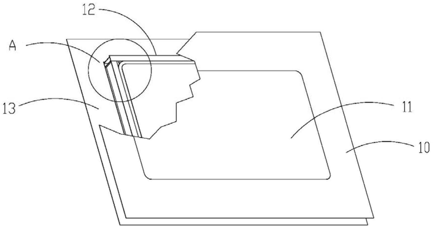 FIG. 1 — Structural view (partially see-through) of the present utility model
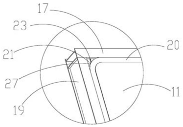 FIG. 2 — Enlarged view of position A in FIG. 1
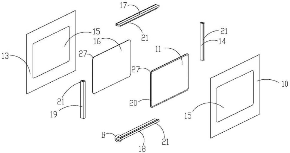 FIG. 3 — Exploded structural view of the present utility model
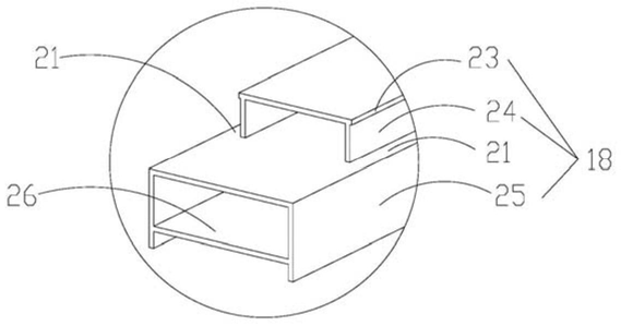 FIG. 4 — Enlarged view of position B in FIG. 3