An Improved Sealing Gasket Structure (Utility Model CN 210317094 U)
The present utility model provides an improved sealing gasket structure. A vertical section A is higher than a vertical section B. A connecting section A includes a first inclined section...
Abstract
The present utility model provides an improved sealing gasket structure. A vertical section A is higher than a vertical section B. A connecting section A includes a first inclined section, a second inclined section, and an arc-shaped connecting section. The arc-shaped connecting section is connected and disposed between the first inclined section and the second inclined section. The first inclined section is connected to the vertical section A and extends beyond the vertical section A. The second inclined section is connected to the vertical section B and extends beyond the vertical section B. In actual use, after the gasket body is clamped in a reserved groove of a clean door frame, the first inclined section and the second inclined section cause the gasket body to fit tightly with the reserved groove and seal the opening of the reserved groove. In combination with the arc-shaped connecting section protruding out of the reserved groove, when the door is closed, the door is in interference contact with the arc-shaped connecting section, thereby achieving further sealing and effectively solving the situation in which a space for bacterial growth or dust accumulation is formed in the reserved groove.
Patent Information
| Item | Detail |
|---|---|
| Issuing authority | National Intellectual Property Administration of the People’s Republic of China (CNIPA) |
| Document type | Utility Model Patent |
| Authorization publication number | CN 210317094 U |
| Authorization publication date | 2020-04-14 |
| Application number | 201920806869.3 |
| Filing date | 2019-05-31 |
| Patentee | Dongguan Pengchi Purification Technology Co., Ltd. |
| Address | Tangyilangwei Road, Tangjiao Village, Chashan Town, Dongguan City, Guangdong Province 523378, China |
| Inventors | Wang Haiou; Hu Guopeng; Li Dexiong |
| Patent agency | Dongguan Yongqiao Intellectual Property Agency (General Partnership) 44400 |
| Patent agent | He Xinhua |
| International Patent Classification (IPC) | E06B 7/23(2006.01) |
| Title of utility model | An Improved Sealing Gasket Structure |
Claims
-
An improved sealing gasket structure, comprising a gasket body (15), characterized in that:
- the cross section of the gasket body comprises a vertical section A (23), a vertical section B (20), a connecting section A (16), and a connecting section B (25), wherein the vertical section A (23), the vertical section B (20), the connecting section A (16), and the connecting section B (25) enclose a buffer inner cavity A;
- the connecting section B (25) is connected between a lower portion of the vertical section A (23) and a lower portion of the vertical section B (20);
- the connecting section A (16) is connected between an upper portion of the vertical section A (23) and an upper portion of the vertical section B (20);
- the vertical section A (23) is higher than the vertical section B (20);
- the connecting section A (16) comprises a first inclined section (24), a second inclined section (18), and an arc-shaped connecting section (17), the arc-shaped connecting section (17) being connected and disposed between the first inclined section (24) and the second inclined section (18);
- the first inclined section (24) is connected to the vertical section A (23) and extends beyond the vertical section A (23); and
- the second inclined section (18) is connected to the vertical section B (20) and extends beyond the vertical section B (20).
-
The improved sealing gasket structure according to claim 1, characterized in that the connecting section B (25) comprises a third inclined section (22), a fourth inclined section (27), and a horizontal connecting section (26), the horizontal connecting section (26) being connected and disposed between the third inclined section (22) and the fourth inclined section (27), the third inclined section (22) being connected to a bottom of the vertical section A (23) and extending beyond the vertical section A (23), and the fourth inclined section (27) being connected to a bottom of the vertical section B (20) and extending beyond the vertical section B (20).
-
The improved sealing gasket structure according to claim 2, characterized in that a plurality of separation strips (19) are disposed in the buffer inner cavity A, and the separation strips (19) divide the buffer inner cavity into a plurality of buffer inner cavities B (21).
-
The improved sealing gasket structure according to claim 3, characterized in that the vertical section A (23) and the vertical section B (20) are disposed parallel to each other.
-
The improved sealing gasket structure according to claim 4, characterized in that a side of each separation strip (19) connected to the vertical section A (23) extends beyond the vertical section A (23).
Description
TECHNICAL FIELD
[0001] The present utility model relates to the technical field of clean door processing, and in particular to an improved sealing gasket structure.
BACKGROUND ART
[0002] At the seam of a clean door frame, a sealing strip is generally clamped therein in order to improve the degree of sealing. A sealing strip structure in the prior art is shown in FIG. 1. A reserved groove (13) is defined on one side of a clean door frame (10), and a sealing strip (12) is clamped in the reserved groove (13). One side of the sealing strip (12) is in close proximity to one side of the reserved groove (13), while a groove A (11) and a groove B (14) are formed between the other side of the sealing strip (12) and the clean door frame (10). Since a clean door has a high cleanliness requirement, in the prior art, spaces for bacterial growth or dust accumulation are formed in the groove A (11) and the groove B (14), which greatly affects the cleanliness of clean door products. This technical problem urgently needs to be solved.
SUMMARY OF THE UTILITY MODEL
[0003] Based on the above, an object of the present utility model is to provide an improved sealing gasket structure, which can tightly seal a reserved groove of a clean door frame and ensure the cleanliness of clean door products.
[0004] The present utility model provides an improved sealing gasket structure, comprising a gasket body. The cross section of the gasket body comprises a vertical section A, a vertical section B, a connecting section A, and a connecting section B. The vertical section A, the vertical section B, the connecting section A, and the connecting section B enclose a buffer inner cavity A. The connecting section B is connected between a lower portion of the vertical section A and a lower portion of the vertical section B, and the connecting section A is connected between an upper portion of the vertical section A and an upper portion of the vertical section B. The vertical section A is higher than the vertical section B. The connecting section A comprises a first inclined section, a second inclined section, and an arc-shaped connecting section, and the arc-shaped connecting section is connected and disposed between the first inclined section and the second inclined section. The first inclined section is connected to the vertical section A and extends beyond the vertical section A. The second inclined section is connected to the vertical section B and extends beyond the vertical section B.
[0005] As a preferred solution, the connecting section B comprises a third inclined section, a fourth inclined section, and a horizontal connecting section. The horizontal connecting section is connected and disposed between the third inclined section and the fourth inclined section. The third inclined section is connected to the bottom of the vertical section A and extends beyond the vertical section A, and the fourth inclined section is connected to the bottom of the vertical section B and extends beyond the vertical section B.
[0006] As a preferred solution, a plurality of separation strips are disposed in the buffer inner cavity A, and the separation strips divide the buffer inner cavity into a plurality of buffer inner cavities B.
[0007] As a preferred solution, the vertical section A and the vertical section B are disposed parallel to each other.
[0008] As a preferred solution, a side of each separation strip connected to the vertical section A extends beyond the vertical section A.
[0009] The present utility model has the following beneficial effects: the vertical section A is higher than the vertical section B; the connecting section A comprises the first inclined section, the second inclined section, and the arc-shaped connecting section; the arc-shaped connecting section is connected and disposed between the first inclined section and the second inclined section; the first inclined section is connected to the vertical section A and extends beyond the vertical section A; and the second inclined section is connected to the vertical section B and extends beyond the vertical section B. In actual use, after the gasket body is clamped in the reserved groove of the clean door frame, the first inclined section and the second inclined section cause the gasket body to fit tightly with the reserved groove and seal the opening of the reserved groove. In combination with the arc-shaped connecting section protruding out of the reserved groove, when the door is closed, the door is in interference contact with the arc-shaped connecting section, thereby achieving further sealing and effectively solving the situation in which a space for bacterial growth or dust accumulation is formed in the reserved groove.
BRIEF DESCRIPTION OF THE DRAWINGS
[0010] FIG. 1 is a schematic structural view of the prior art.
[0011] FIG. 2 is a schematic structural view of the present utility model.
[0012] FIG. 3 is a schematic cross-sectional structural view of the present utility model.
[0013] FIG. 4 is a schematic cross-sectional structural view of the present utility model in a use state.
[0014] FIG. 5 is an enlarged view of position A in FIG. 2.
[0015] The reference numerals are as follows: clean door frame (10), groove A (11), sealing strip (12), reserved groove (13), groove B (14), gasket body (15), connecting section A (16), second inclined section (18), arc-shaped connecting section (17), separation strip (19), vertical section B (20), buffer inner cavity B (21), third inclined section (22), vertical section A (23), first inclined section (24), connecting section B (25), fourth inclined section (27), and horizontal connecting section (26).
DETAILED DESCRIPTION OF EMBODIMENTS
[0016] In order to further understand the features, technical means, and specific objects and functions achieved by the present utility model, the present utility model is described in further detail below with reference to the accompanying drawings and specific embodiments.
[0017] Referring to FIGS. 2-5, an improved sealing gasket structure comprises a gasket body (15). The gasket body is an integrally injection-molded structure made of soft rubber. The cross section of the gasket body comprises a vertical section A (23), a vertical section B (20), a connecting section A (16), and a connecting section B (25). The vertical section A (23), the vertical section B (20), the connecting section A (16), and the connecting section B (25) enclose a buffer inner cavity A, and the vertical section A (23) and the vertical section B (20) are disposed parallel to each other. The connecting section B (25) is connected between the lower portion of the vertical section A (23) and the lower portion of the vertical section B (20), and the connecting section A (16) is connected between the upper portion of the vertical section A (23) and the upper portion of the vertical section B (20). The vertical section A (23) is higher than the vertical section B (20). The connecting section A (16) comprises a first inclined section (24), a second inclined section (18), and an arc-shaped connecting section (17), and the arc-shaped connecting section (17) is connected and disposed between the first inclined section (24) and the second inclined section (18). The first inclined section (24) is connected to the vertical section A (23) and extends beyond the vertical section A (23), and the second inclined section (18) is connected to the vertical section B (20) and extends beyond the vertical section B (20). The connecting section B (25) comprises a third inclined section (22), a fourth inclined section (27), and a horizontal connecting section (26), and the horizontal connecting section (26) is connected and disposed between the third inclined section (22) and the fourth inclined section (27). The third inclined section (22) is connected to the bottom of the vertical section A (23) and extends beyond the vertical section A (23), and the fourth inclined section (27) is connected to the bottom of the vertical section B (20) and extends beyond the vertical section B (20). With this structural arrangement, the portion of the third inclined section (22) extending beyond the vertical section A (23) abuts against an inner groove wall of the reserved groove, and the portion of the fourth inclined section (27) extending beyond the vertical section B (20) abuts against the inner groove wall of the reserved groove, so that the gasket body can be embedded in the reserved groove more firmly.
[0018] A plurality of separation strips (19) are disposed in the buffer inner cavity A, and the separation strips (19) divide the buffer inner cavity into a plurality of buffer inner cavities B (21). By providing the buffer inner cavities B (21), the side of each separation strip (19) connected to the vertical section A (23) extends beyond the vertical section A (23), so that the gasket body has a good buffering function and material is also saved.
[0019] In this embodiment, the vertical section A is higher than the vertical section B; the connecting section A comprises the first inclined section, the second inclined section, and the arc-shaped connecting section; the arc-shaped connecting section is connected and disposed between the first inclined section and the second inclined section; the first inclined section is connected to the vertical section A and extends beyond the vertical section A; and the second inclined section is connected to the vertical section B and extends beyond the vertical section B. In actual use, after the gasket body is clamped in the reserved groove of the clean door frame, the first inclined section and the second inclined section cause the gasket body to fit tightly with the reserved groove and seal the opening of the reserved groove. In combination with the arc-shaped connecting section protruding out of the reserved groove, when the door is closed, the door is in interference contact with the arc-shaped connecting section, thereby achieving further sealing and effectively solving the situation in which a space for bacterial growth or dust accumulation is formed in the reserved groove.
[0020] The above embodiments only describe one embodiment of the present utility model, and the description thereof is relatively specific and detailed. However, this should not be construed as a limitation on the patent scope of the present utility model. It should be noted that, for a person of ordinary skill in the art, without departing from the concept of the present utility model, several modifications and improvements can be made, all of which fall within the protection scope of the present utility model. Therefore, the protection scope of the present utility model patent shall be defined by the appended claims.
Drawings
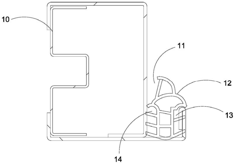 FIG. 1 — Schematic structural view of the prior art
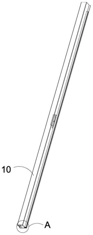 FIG. 2 — Schematic structural view of the present utility model
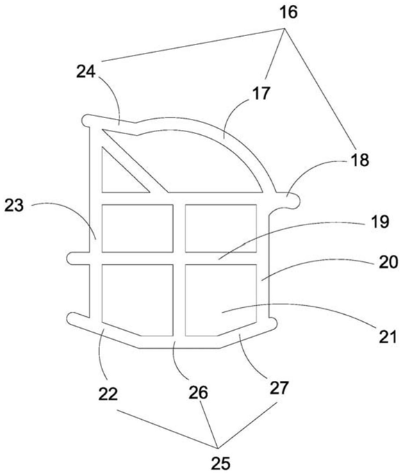 FIG. 3 — Schematic cross-sectional structural view of the present utility model
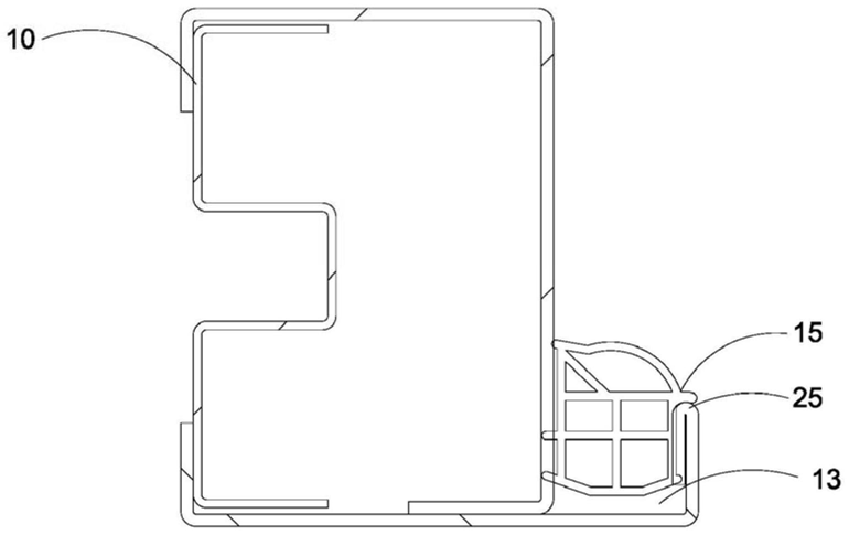 FIG. 4 — Schematic cross-sectional structural view of the present utility model in a use state
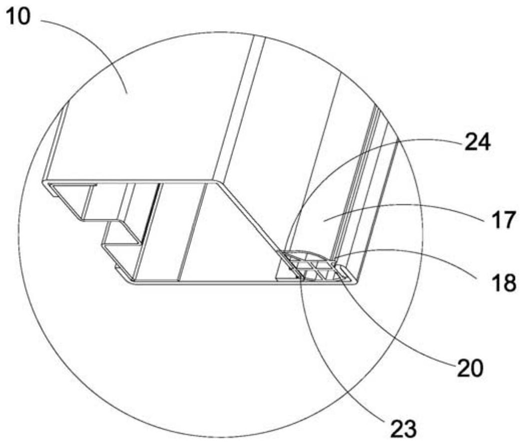 FIG. 5 — Enlarged view of position A in FIG. 2