A Uniform-Flow Membrane Structure for Supply Air Ceiling (Utility Model CN 210141630 U)
The present utility model provides a uniform-flow membrane structure for a supply air ceiling, comprising a mounting frame and a uniform-flow membrane, wherein the mounting frame comprises...
Abstract
The present utility model provides a uniform-flow membrane structure for a supply air ceiling, comprising a mounting frame and a uniform-flow membrane, wherein the mounting frame comprises a rectangular frame and a surrounding frame; clamping structures are fixedly provided at corner positions of the rectangular frame adjacent to the surrounding frame, and the uniform-flow membrane is covered and arranged between the rectangular frame and the clamping structures; each clamping structure comprises a screw, a vertical spring strip and a horizontal spring strip, one end of the vertical spring strip is arranged below the horizontal spring strip, and the screw successively penetrates the horizontal spring strip and the vertical spring strip to be fixed with the rectangular frame; a free end of the vertical spring strip is in pressing contact with the uniform-flow membrane, and a free end of the horizontal spring strip is in pressing contact with the uniform-flow membrane; suspension protruding plates perpendicular to the surrounding frame are arranged on two opposite sides of the surrounding frame. The mounting frame is arranged to cooperate with the uniform-flow membrane, and the uniform-flow membrane is clamped and fixed by the mounting frame, so that convenient installation and disassembly are achieved.
Patent Information
| Item | Detail |
|---|---|
| Issuing authority | National Intellectual Property Administration of the People’s Republic of China (CNIPA) |
| Document type | Utility Model Patent |
| Authorization publication number | CN 210141630 U |
| Authorization publication date | 2020.03.13 |
| Application number | 201920993182.5 |
| Filing date | 2019.06.28 |
| Patentee | Dongguan Pengchi Purification Technology Co., Ltd. |
| Address | Tangyilangwei Road, Tangjiao Village, Chashan Town, Dongguan City, Guangdong Province 523378, China |
| Inventors | Hu Guopeng |
| Patent agency | Dongguan Yongqiao Intellectual Property Agency (General Partnership) 44400 |
| Patent agent | He Xinhua |
| International Patent Classification (IPC) | F24F 1/0011(2019.01); F24F 13/06(2006.01) |
| Title of utility model | A Uniform-Flow Membrane Structure for Supply Air Ceiling |
Claims
-
A uniform-flow membrane structure for a supply air ceiling, comprising:
- a mounting frame (23) and a uniform-flow membrane (10), the mounting frame (23) comprising a rectangular frame (17) and a surrounding frame (11) surrounding four sides of the rectangular frame (17) and forming a perpendicular relationship with the rectangular frame (17);
- clamping structures (24) fixedly arranged at corner positions of the rectangular frame (17) adjacent to the surrounding frame (11), the uniform-flow membrane (10) being covered and arranged between the rectangular frame (17) and the clamping structures (24);
- each clamping structure (24) comprising a screw (14), a vertical spring strip (13) and a horizontal spring strip (15), one end of the vertical spring strip (13) being arranged below the horizontal spring strip (15), the screw (14) successively penetrating the horizontal spring strip (15) and the vertical spring strip (13) to be fixed with the rectangular frame (17);
- a free end of the vertical spring strip (13) being in pressing contact with the uniform-flow membrane (10), and a free end of the horizontal spring strip (15) being in pressing contact with the uniform-flow membrane (10); and
- suspension protruding plates (12) forming a perpendicular relationship with the surrounding frame (11) being arranged on two opposite sides of the surrounding frame (11).
-
The uniform-flow membrane structure for a supply air ceiling according to claim 1, characterized in that four clamping structures (24) are provided.
-
The uniform-flow membrane structure for a supply air ceiling according to claim 1, characterized in that the vertical spring strip (13) is integrally formed from a mounting section (22), an inclined section (21) and a T-shaped pressing section (20), the inclined section (21) connecting the mounting section (22) and the T-shaped pressing section (20) together; and a screw hole matched with the screw (14) is formed in the mounting section (22).
-
The uniform-flow membrane structure for a supply air ceiling according to claim 1, characterized in that the horizontal spring strip (15) is integrally formed from a mounting section (22), an inclined section (21) and a T-shaped pressing section (20), the inclined section (21) connecting the mounting section (22) and the T-shaped pressing section (20) together; and a screw hole matched with the screw (14) is formed in the mounting section (22).
-
The uniform-flow membrane structure for a supply air ceiling according to claim 1, characterized in that positioning protruding posts (16) are arranged on each strip-shaped surface of the mounting frame (23), and the uniform-flow membrane (10) is provided with through holes for the protruding posts (16) to pass through.
-
The uniform-flow membrane structure for a supply air ceiling according to claim 1, characterized in that a surface of the mounting frame (23) is coated with an anti-static film layer.
-
The uniform-flow membrane structure for a supply air ceiling according to claim 5, characterized in that a free end of each protruding post (16) is sleeved with a compression nut.
-
The uniform-flow membrane structure for a supply air ceiling according to claim 1, characterized in that a thickness of the uniform-flow membrane (10) is set to 0.2-0.5 mm.
Description
TECHNICAL FIELD
[0001] The present utility model relates to the technical field of laminar flow supply air ceilings, and in particular to a uniform-flow membrane structure for a supply air ceiling.
BACKGROUND ART
[0002] A laminar flow supply air ceiling is a purification device necessarily used in modern hospital operating rooms, and is widely applied in projects such as hospital clean operating rooms, clean wards and clean animal rooms. A uniform-flow membrane is often used at an air outlet of the laminar flow supply air ceiling; the function of the uniform-flow membrane is mainly reflected in flow equalization, i.e. making the airflow coming down from the HEPA filter at the air outlet uniformly press downward in layers without forming a turbulent state, thereby better controlling the cleanliness to achieve Class 10,000, Class 1,000 and Class 100 effects. Currently, the uniform-flow membrane is mainly attached to a perforated plate at the air outlet; when replacement is required, the perforated plate has to be removed and the uniform-flow membrane scraped off, or a perforated plate has to be replaced directly, and such an operation is too environmentally unfriendly. In view of this situation, the uniform-flow membrane structure used in cooperation with the laminar flow supply air ceiling urgently needs improvement.
SUMMARY OF THE UTILITY MODEL
[0003] Based on this, an object of the present utility model is to provide a uniform-flow membrane structure for a supply air ceiling, in which a mounting frame is arranged to cooperate with a uniform-flow membrane, and the uniform-flow membrane is clamped and fixed by the mounting frame, so that convenient installation and disassembly are achieved.
[0004] The present utility model provides a uniform-flow membrane structure for a supply air ceiling, comprising a mounting frame and a uniform-flow membrane, wherein the mounting frame comprises a rectangular frame and a surrounding frame surrounding four sides of the rectangular frame and forming a perpendicular relationship with the rectangular frame; clamping structures are fixedly arranged at corner positions of the rectangular frame adjacent to the surrounding frame, and the uniform-flow membrane is covered and arranged between the rectangular frame and the clamping structures; each clamping structure comprises a screw, a vertical spring strip and a horizontal spring strip, one end of the vertical spring strip is arranged below the horizontal spring strip, and the screw successively penetrates the horizontal spring strip and the vertical spring strip to be fixed with the rectangular frame; a free end of the vertical spring strip is in pressing contact with the uniform-flow membrane, and a free end of the horizontal spring strip is in pressing contact with the uniform-flow membrane; suspension protruding plates perpendicular to the surrounding frame are arranged on two opposite sides of the surrounding frame.
[0005] As a preferred solution, four clamping structures are provided.
[0006] As a preferred solution, the vertical spring strip is integrally formed from a mounting section, an inclined section and a T-shaped pressing section, the inclined section connecting the mounting section and the T-shaped pressing section together; and a screw hole matched with the screw is formed in the mounting section.
[0007] As a preferred solution, the horizontal spring strip is integrally formed from a mounting section, an inclined section and a T-shaped pressing section, the inclined section connecting the mounting section and the T-shaped pressing section together; and a screw hole matched with the screw is formed in the mounting section.
[0008] As a preferred solution, positioning protruding posts are arranged on each strip-shaped surface of the mounting frame, and the uniform-flow membrane is provided with through holes for the protruding posts to pass through.
[0009] As a preferred solution, a surface of the mounting frame is coated with an anti-static film layer.
[0010] As a preferred solution, a free end of each protruding post is sleeved with a compression nut.
[0011] As a preferred solution, a thickness of the uniform-flow membrane is set to 0.2-0.5 mm.
[0012] The present utility model has the following beneficial effects:
[0013] 1. The uniform-flow membrane is covered and arranged between the rectangular frame and the clamping structures; a free end of the vertical spring strip is in pressing contact with the uniform-flow membrane, and a free end of the horizontal spring strip is in pressing contact with the uniform-flow membrane, so that the uniform-flow membrane is in close contact with the rectangular frame; suspension protruding plates perpendicular to the surrounding frame are arranged on two opposite sides of the surrounding frame, the suspension protruding plates cooperate with the air outlet of the laminar flow supply air ceiling and are correspondingly embedded in reserved grooves of the air outlet of the laminar flow supply air ceiling; if the mounting frame needs to be removed, the suspension protruding plates can be directly lifted, and disassembly is convenient; moreover, when the uniform-flow membrane needs to be replaced, the vertical spring strip and the horizontal spring strip are successively pulled up, and then the uniform-flow membrane can be taken out, which is convenient and quick, saves replacement time and improves working efficiency;
[0014] 2. Positioning protruding posts are arranged on each strip-shaped surface of the mounting frame, and the uniform-flow membrane is provided with through holes for the protruding posts to pass through; through cooperation of the protruding posts and the through holes, the uniform-flow membrane can be accurately clamped on the mounting frame, reducing debugging time;
[0015] 3. A free end of each protruding post is sleeved with a compression nut, and the uniform-flow membrane is pressed on the mounting frame by the nut, further strengthening fixation of the uniform-flow membrane;
[0016] 4. A surface of the mounting frame is coated with an anti-static film layer, so that the surface of the mounting frame has an anti-static function.
BRIEF DESCRIPTION OF THE DRAWINGS
[0017] FIG. 1 is a structural view of the present utility model.
[0018] FIG. 2 is a structural view of the mounting frame.
[0019] FIG. 3 is a side view of the clamping structure.
[0020] The reference signs are as follows: uniform-flow membrane 10; surrounding frame 11; screw 14; vertical spring strip 13; horizontal spring strip 15; suspension protruding plate 12; rectangular frame 17; positioning protruding post 16; mounting section 22; inclined section 21; T-shaped pressing section 20; mounting frame 23; clamping structure 24.
DETAILED DESCRIPTION OF EMBODIMENTS
[0021] For a further understanding of the features, technical means, and specific objects and functions achieved by the present utility model, the present utility model will be described in further detail below with reference to the accompanying drawings and specific embodiments.
[0022] Referring to FIGS. 1-3, a uniform-flow membrane structure for a supply air ceiling comprises a mounting frame 23 and a uniform-flow membrane 10; the mounting frame 23 comprises a rectangular frame 17 and a surrounding frame 11 surrounding four sides of the rectangular frame 17 and forming a perpendicular relationship with the rectangular frame 17; clamping structures 24 are fixedly arranged at corner positions of the rectangular frame 17 adjacent to the surrounding frame 11; in this embodiment, four clamping structures 24 are provided; the uniform-flow membrane 10 is covered and arranged between the rectangular frame 17 and the clamping structures 24, and four corner positions of the uniform-flow membrane 10 are each provided with a recessed position matched with the corresponding clamping structure 24; each clamping structure 24 comprises a screw 14, a vertical spring strip 13 and a horizontal spring strip 15, one end of the vertical spring strip 13 is arranged below the horizontal spring strip 15, and the screw 14 successively penetrates the horizontal spring strip 15 and the vertical spring strip 13 to be fixed with the rectangular frame 17; a free end of the vertical spring strip 13 is in pressing contact with the uniform-flow membrane 10, and a free end of the horizontal spring strip 15 is in pressing contact with the uniform-flow membrane 10; suspension protruding plates 12 perpendicular to the surrounding frame 11 are arranged on two opposite sides of the surrounding frame 11.
[0023] The vertical spring strip 13 is integrally formed from a mounting section 22, an inclined section 21 and a T-shaped pressing section 20, the inclined section 21 connecting the mounting section 22 and the T-shaped pressing section 20 together; a screw hole matched with the screw 14 is formed in the mounting section 22; the horizontal spring strip 15 is integrally formed from a mounting section 22, an inclined section 21 and a T-shaped pressing section 20, the inclined section 21 connecting the mounting section 22 and the T-shaped pressing section 20 together; a screw hole matched with the screw 14 is formed in the mounting section 22; and the T-shaped pressing section 20 presses the laminar flow membrane on the rectangular frame 17.
[0024] As a preferred embodiment, positioning protruding posts 16 are arranged on each strip-shaped surface of the mounting frame 23, and the uniform-flow membrane 10 is provided with through holes for the protruding posts 16 to pass through; through cooperation of the protruding posts and the through holes, the uniform-flow membrane can be accurately clamped on the mounting frame, reducing debugging time.
[0025] As a preferred embodiment, a surface of the mounting frame 23 is coated with an anti-static film layer.
[0026] As a preferred embodiment, a free end of each protruding post 16 is sleeved with a compression nut, and the uniform-flow membrane is pressed on the mounting frame by the nut, further strengthening fixation of the uniform-flow membrane.
[0027] The thickness of the uniform-flow membrane 10 is set to 0.2-0.5 mm; in this embodiment, the thickness of the uniform-flow membrane 10 is set to 0.35 mm.
[0028] In this embodiment, the uniform-flow membrane is covered and arranged between the rectangular frame and the clamping structures; a free end of the vertical spring strip is in pressing contact with the uniform-flow membrane, and a free end of the horizontal spring strip is in pressing contact with the uniform-flow membrane, so that the uniform-flow membrane is in close contact with the rectangular frame; suspension protruding plates perpendicular to the surrounding frame are arranged on two opposite sides of the surrounding frame, the suspension protruding plates cooperate with the air outlet of the laminar flow supply air ceiling and are correspondingly embedded in reserved grooves of the air outlet of the laminar flow supply air ceiling; if the mounting frame needs to be removed, the suspension protruding plates can be directly lifted, and disassembly is convenient; moreover, when the uniform-flow membrane needs to be replaced, the vertical spring strip and the horizontal spring strip are successively pulled up, and then the uniform-flow membrane can be taken out, which is convenient and quick, saves replacement time and improves working efficiency.
[0029] The above embodiments merely express several embodiments of the present utility model, and the description thereof is relatively specific and detailed, but it should not be construed as limiting the patent scope of the present utility model. It should be noted that those of ordinary skill in the art may make several modifications and improvements without departing from the concept of the present utility model, and these shall all fall within the protection scope of the present utility model. Therefore, the protection scope of the present utility model patent shall be defined by the appended claims.
Drawings
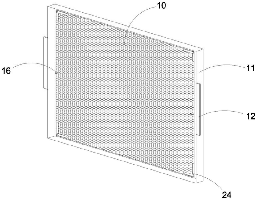 FIG. 1 — Structural view of the uniform-flow membrane structure
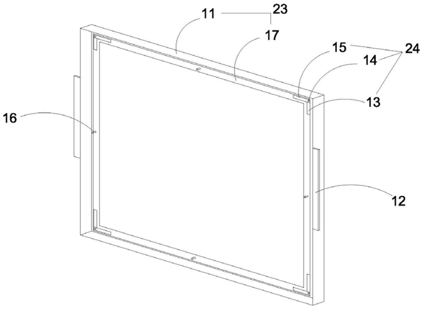 FIG. 2 — Structural view of the mounting frame
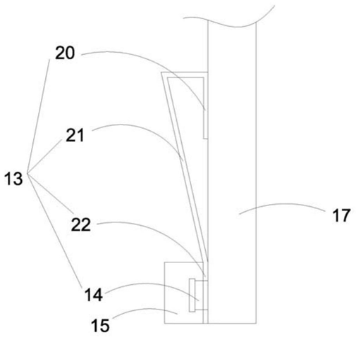 FIG. 3 — Side view of the clamping structure