Air Purification Unit (Utility Model CN 210141666 U)
The present utility model provides an air purification unit, comprising a cabinet. A dust removal zone is provided in the cabinet; a dust collection zone and a light source installation...
Abstract
The present utility model provides an air purification unit, comprising a cabinet. A dust removal zone is provided in the cabinet; a dust collection zone and a light source installation zone are provided at the lower side of the dust removal zone; an equipment zone is provided at the lower sides of the dust collection zone and the light source installation zone. The cabinet is provided with a louver and an air outlet, and the louver and the air outlet are located on two sides of the dust removal zone respectively. A honeycomb dust barrier, a multi-ejector push plate, a bag-type dust removal group and a fan are sequentially provided in the dust removal zone; a drive assembly is provided at the top of the dust removal zone, and an output end of the drive assembly is connected to the top end of the multi-ejector push plate. A drawer-type dust collection cabinet is provided in the dust collection zone, and the drawer-type dust collection cabinet is located at the lower side of the honeycomb dust barrier. An ultraviolet lamp is provided in the light source installation zone, and a glass light-transmitting plate is provided at the upper side of the ultraviolet lamp. The air purification unit of the present utility model has high dust removal efficiency.
Patent Information
| Item | Detail |
|---|---|
| Issuing authority | National Intellectual Property Administration of the People’s Republic of China (CNIPA) |
| Document type | Utility Model Patent |
| Authorization publication number | CN 210141666 U |
| Authorization publication date | 2020.03.13 |
| Application number | 201920993159.6 |
| Filing date | 2019.06.28 |
| Patentee | Dongguan Pengchi Purification Technology Co., Ltd. |
| Address | Tangyilangwei Road, Tangjiao Village, Chashan Town, Dongguan City, Guangdong Province 523378, China |
| Inventors | Hu Guopeng |
| Patent agency | Dongguan Yongqiao Intellectual Property Agency (General Partnership) 44400 |
| Patent agent | He Xinhua |
| International Patent Classification (IPC) | F24F 3/16(2006.01); F24F 13/20(2006.01); F24F 13/08(2006.01); F24F 11/523(2018.01); F24F 110/10(2018.01); F24F 110/20(2018.01) |
| Title of utility model | Air Purification Unit |
Claims
-
An air purification unit, comprising:
- a cabinet (1), wherein a dust removal zone (11) is provided in the cabinet (1), a dust collection zone (12) and a light source installation zone (13) are provided at the lower side of the dust removal zone (11), and an equipment zone (14) is provided at the lower sides of the dust collection zone (12) and the light source installation zone (13);
- the cabinet (1) is provided with a louver (101) and an air outlet (102), and the louver (101) and the air outlet (102) are located on two sides of the dust removal zone (11) respectively;
- a honeycomb dust barrier (2), a multi-ejector push plate (3), a bag-type dust removal group (4) and a fan (5) are sequentially provided in the dust removal zone (11); a drive assembly (6) is provided at the top of the dust removal zone (11), and an output end of the drive assembly (6) is connected to the top end of the multi-ejector push plate (3);
- a drawer-type dust collection cabinet (7) is provided in the dust collection zone (12), and the drawer-type dust collection cabinet (7) is located at the lower side of the honeycomb dust barrier (2);
- and an ultraviolet lamp (81) is provided in the light source installation zone (13), and a glass light-transmitting plate (82) is provided at the upper side of the ultraviolet lamp (81).
-
The air purification unit according to claim 1, characterized in that the honeycomb dust barrier (2) comprises a first frame (21) and a support (22) fixed in the first frame (21), a plurality of honeycomb holes (23) are provided in the support (22), a downwardly recessed dust collection bag (24) is provided in each honeycomb hole (23); the multi-ejector push plate (3) comprises a second frame (31), a support bar (32) fixed in the second frame (31), and a plurality of ejector pins (33) fixed on the support bar (32) and corresponding to the honeycomb holes (23).
-
The air purification unit according to claim 1, characterized in that the drive assembly (6) comprises a motor (61), a lead screw (62) connected to an output shaft of the motor (61), and a sliding block (63) slidably connected to the lead screw (62), and the sliding block (63) is the output end of the drive assembly (6).
-
The air purification unit according to claim 1, characterized in that an electric control box (91) is provided in the equipment zone (14), a touch-screen display panel (92) is further provided on the cabinet (1), and the touch-screen display panel (92) is located on one side of the equipment zone (14).
-
The air purification unit according to claim 4, characterized in that a temperature sensor (93) and a humidity sensor (94) are further provided on one side of the touch-screen display panel (92).
Description
TECHNICAL FIELD
[0001] The present utility model relates to the technical field of filters, and in particular to an air purification unit.
BACKGROUND ART
[0002] An air purifier, also known as an air cleaner, air freshener or purifier, refers to a device capable of adsorbing, decomposing or converting various air pollutants (generally including PM2.5, dust, pollen, odors, decoration pollution such as formaldehyde, bacteria, allergens and the like) and effectively improving air cleanliness. Existing air purification units generally consist of a single-layer or multi-layer filter element combined with a fan; the equipment is simple, the dust removal efficiency is low, and the filter element tends to accumulate dust and is difficult to clean.
SUMMARY OF THE UTILITY MODEL
[0003] In view of the above problems, the present utility model provides an air purification unit with high dust removal efficiency.
[0004] To achieve the above object, the present utility model solves the above technical problem by the following technical solutions:
[0005] An air purification unit comprises a cabinet. A dust removal zone is provided in the cabinet; a dust collection zone and a light source installation zone are provided at the lower side of the dust removal zone; an equipment zone is provided at the lower sides of the dust collection zone and the light source installation zone. The cabinet is provided with a louver and an air outlet, and the louver and the air outlet are located on two sides of the dust removal zone respectively. A honeycomb dust barrier, a multi-ejector push plate, a bag-type dust removal group and a fan are sequentially provided in the dust removal zone; a drive assembly is provided at the top of the dust removal zone, and an output end of the drive assembly is connected to the top end of the multi-ejector push plate. A drawer-type dust collection cabinet is provided in the dust collection zone, and the drawer-type dust collection cabinet is located at the lower side of the honeycomb dust barrier. An ultraviolet lamp is provided in the light source installation zone, and a glass light-transmitting plate is provided at the upper side of the ultraviolet lamp.
[0006] Specifically, the honeycomb dust barrier comprises a first frame and a support fixed in the first frame; a plurality of honeycomb holes are provided in the support, a downwardly recessed dust collection bag is provided in each honeycomb hole; the multi-ejector push plate comprises a second frame, a support bar fixed in the second frame, and a plurality of ejector pins fixed on the support bar and corresponding to the honeycomb holes.
[0007] Specifically, the drive assembly comprises a motor, a lead screw connected to an output shaft of the motor, and a sliding block slidably connected to the lead screw, and the sliding block is the output end of the drive assembly.
[0008] Specifically, an electric control box is provided in the equipment zone; a touch-screen display panel is further provided on the cabinet, and the touch-screen display panel is located on one side of the equipment zone.
[0009] Specifically, a temperature sensor and a humidity sensor are further provided on one side of the touch-screen display panel.
[0010] The present utility model has the following beneficial effects:
[0011] First, the air purification unit of the present utility model is additionally provided with a honeycomb dust barrier and a multi-ejector push plate, and a drawer-type dust collection cabinet is additionally provided at the lower side of the honeycomb dust barrier; through the pushing of the ejector pins of the multi-ejector push plate, large-particle dust in the dust collection bags falls into the drawer-type dust collection cabinet, facilitating cleaning;
[0012] Second, a bag-type dust removal group is added, which effectively blocks dust by means of multiple layers of bags, so that most dust cannot pass through, and the dust removal efficiency is high.
BRIEF DESCRIPTION OF THE DRAWINGS
[0013] FIG. 1 is a front view of an air purification unit of the present utility model;
[0014] FIG. 2 is a cross-sectional view taken along plane A-A in FIG. 1;
[0015] FIG. 3 is an enlarged view of part B in FIG. 2;
[0016] FIG. 4 is a structural schematic view of a honeycomb dust barrier of the present utility model;
[0017] FIG. 5 is a structural schematic view of a multi-ejector push plate of the present utility model;
[0018] FIG. 6 is a structural schematic view of dust collection bags and ejector pins of the present utility model;
[0019] The reference numerals are as follows: cabinet 1; dust removal zone 11; dust collection zone 12; light source installation zone 13; equipment zone 14; louver 101; air outlet 102; honeycomb dust barrier 2; first frame 21; support 22; honeycomb holes 23; dust collection bag 24; multi-ejector push plate 3; second frame 31; support bar 32; ejector pin 33; bag-type dust removal group 4; fan 5; drive assembly 6; motor 61; lead screw 62; sliding block 63; drawer-type dust collection cabinet 7; ultraviolet lamp 81; glass light-transmitting plate 82; electric control box 91; touch-screen display panel 92; temperature sensor 93; humidity sensor 94.
DETAILED DESCRIPTION OF EMBODIMENTS
[0020] The present utility model is described in further detail below with reference to the embodiments and the accompanying drawings, but the embodiments of the present utility model are not limited thereto.
[0021] As shown in FIGS. 1-6:
[0022] An air purification unit comprises a cabinet 1. A dust removal zone 11 is provided in the cabinet 1; a dust collection zone 12 and a light source installation zone 13 are provided at the lower side of the dust removal zone 11; an equipment zone 14 is provided at the lower sides of the dust collection zone 12 and the light source installation zone 13. The cabinet 1 is provided with a louver 101 and an air outlet 102, and the louver 101 and the air outlet 102 are located on two sides of the dust removal zone 11 respectively. A honeycomb dust barrier 2, a multi-ejector push plate 3, a bag-type dust removal group 4 and a fan 5 are sequentially provided in the dust removal zone 11. The bag-type dust removal group 4 consists of a plurality of bags fixed in the dust removal zone 11, and each bag consists of a metal support and a cloth covering the outer side of the metal support. When the fan 5 operates, air first passes through the honeycomb dust barrier 2; large-particle dust and suspended matter are collected in the dust collection bags 24 of the honeycomb dust barrier 2; small-particle dust, suspended matter, bacteria and the like continue to move along the airflow direction; the small-particle dust and suspended matter are blocked by the bag-type dust removal group 4, and the bacteria are killed by ultraviolet rays. A drive assembly 6 is provided at the top of the dust removal zone 11, and an output end of the drive assembly 6 is connected to the top end of the multi-ejector push plate 3. A drawer-type dust collection cabinet 7 is provided in the dust collection zone 12, and the drawer-type dust collection cabinet 7 is located at the lower side of the honeycomb dust barrier 2. An ultraviolet lamp 81 is provided in the light source installation zone 13, and a glass light-transmitting plate 82 is provided at the upper side of the ultraviolet lamp 81. Ultraviolet rays emitted by the ultraviolet lamp 81 pass through the glass light-transmitting plate 82 and irradiate the interior of the dust removal zone 11, and the ultraviolet rays can kill part of the bacteria in the air, thereby achieving a bacteria-removing effect.
[0023] Preferably, the honeycomb dust barrier 2 comprises a first frame 21 and a support 22 fixed in the first frame 21; a plurality of honeycomb holes 23 are provided in the support 22, and a downwardly recessed dust collection bag 24 is provided in each honeycomb hole 23. The multi-ejector push plate 3 comprises a second frame 31, a support bar 32 fixed in the second frame 31, and a plurality of ejector pins 33 fixed on the support bar 32 and corresponding to the honeycomb holes 23. Under the driving action of the drive assembly 6, the multi-ejector push plate 3 can be moved toward the honeycomb dust barrier 2, and the ejector pins 33 eject the dust in the dust collection bags 24 so that the dust falls into the drawer-type dust collection cabinet 7 for collection.
[0024] Preferably, the drive assembly 6 comprises a motor 61, a lead screw 62 connected to an output shaft of the motor 61, and a sliding block 63 slidably connected to the lead screw 62, and the sliding block 63 is the output end of the drive assembly 6.
[0025] Preferably, an electric control box 91 is provided in the equipment zone 14; a touch-screen display panel 92 is further provided on the cabinet 1; the touch-screen display panel 92 is located on one side of the equipment zone 14, and parameters such as indoor temperature and humidity can be displayed on the touch-screen display panel 92.
[0026] Preferably, a temperature sensor 93 and a humidity sensor 94 are further provided on one side of the touch-screen display panel 92. The temperature sensor 93 and the humidity sensor 94 are used to detect the indoor temperature and humidity, and then feed the information back to the touch-screen display panel 92 for display.
[0027] The above embodiments only express one embodiment of the present utility model, and the description thereof is relatively specific and detailed, but it should not be construed as limiting the patent scope of the present utility model. It should be noted that, for those of ordinary skill in the art, without departing from the concept of the present utility model, several modifications and improvements can be made, all of which fall within the protection scope of the present utility model. Therefore, the protection scope of the present utility model patent shall be subject to the appended claims.
Drawings
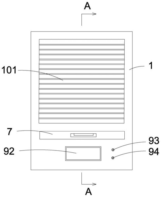 FIG. 1 - front view of the air purification unit
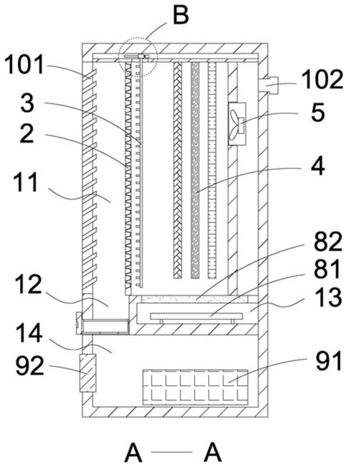 FIG. 2 - cross-sectional view taken along plane A-A in FIG. 1
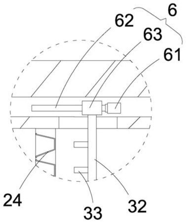 FIG. 3 - enlarged view of part B in FIG. 2
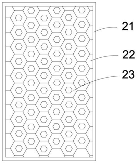 FIG. 4 - structural schematic view of the honeycomb dust barrier
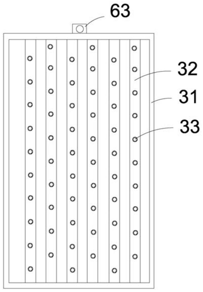 FIG. 5 - structural schematic view of the multi-ejector push plate
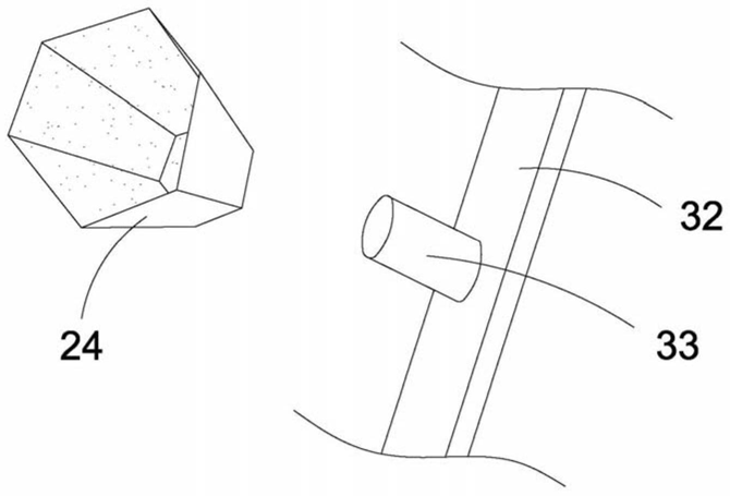 FIG. 6 - structural schematic view of the dust collection bags and ejector pins