Three-Door Electronic-Interlocking Pass-Through Box (Utility Model CN 210750384 U)
The present utility model provides a three-door electronic-interlocking pass-through box, comprising a box body. The box body has a first opening, a second opening and a third opening, and...
Abstract
The present utility model provides a three-door electronic-interlocking pass-through box, comprising a box body. The box body has a first opening, a second opening and a third opening, and a first door panel, a second door panel and a third door panel are provided on the first opening, the second opening and the third opening respectively. A first electronic interlocking device, a second electronic interlocking device and a third electronic interlocking device are provided on the box body; an ultraviolet germicidal lamp is provided at an upper end inside the box body; a cavity is provided at the bottom of the box body, and an ozone generator is provided in the cavity; air holes communicating with the cavity are provided at the bottoms of the inner sides of the first opening, the second opening and the third opening. The three-door electronic-interlocking pass-through box of the present utility model has three door panels, enables transfer among a non-clean area, a clean area and another clean area, and minimizes contamination of the clean areas.
Patent Information
| Item | Detail |
|---|---|
| Issuing authority | National Intellectual Property Administration of the People’s Republic of China (CNIPA) |
| Document type | Utility Model Patent |
| Authorization publication number | CN 210750384 U |
| Authorization publication date | 2020.06.16 |
| Application number | 201920992532.6 |
| Filing date | 2019.06.28 |
| Patentee | Dongguan Pengchi Purification Technology Co., Ltd. |
| Address | Tangyilangwei Road, Tangjiao Village, Chashan Town, Dongguan City, Guangdong Province 523378, China |
| Inventors | Hu Guopeng |
| Patent agency | Dongguan Yongqiao Intellectual Property Agency (General Partnership) 44400 |
| Patent agent | He Xinhua |
| International Patent Classification (IPC) | A61L 2/10(2006.01); A61L 2/20(2006.01); A61L 2/26(2006.01); E05B 63/14(2006.01); E05B 17/22(2006.01) |
| Title of utility model | Three-Door Electronic-Interlocking Pass-Through Box |
Claims
-
A three-door electronic-interlocking pass-through box, comprising:
- a box body (1), wherein the box body (1) has a first opening (11), a second opening (12) and a third opening (13), and a first door panel (14), a second door panel (15) and a third door panel (16) are provided on the first opening (11), the second opening (12) and the third opening (13) respectively;
- a first electronic interlocking device (2), a second electronic interlocking device (3) and a third electronic interlocking device are provided on the box body (1); a first lock groove matched with the first electronic interlocking device (2) is provided on the first door panel (14), a second lock groove matched with the second electronic interlocking device (3) is provided on the second door panel (15), and a third lock groove matched with the third electronic interlocking device is provided on the third door panel (16);
- an ultraviolet germicidal lamp (4) is provided at an upper end inside the box body (1); a cavity is provided at the bottom of the box body (1), and an ozone generator (5) is provided in the cavity; and air holes (17) communicating with the cavity are provided at the bottoms of the inner sides of the first opening (11), the second opening (12) and the third opening (13).
-
The three-door electronic-interlocking pass-through box according to claim 1, characterized in that a first photoelectric sensor (6) is provided at the inner side of the first opening (11), a first light shielding plate (7) corresponding to the first photoelectric sensor (6) is provided at the inner side of the first door panel (14), a second photoelectric sensor is provided at the inner side of the second opening (12), a second light shielding plate corresponding to the second photoelectric sensor is provided at the inner side of the second door panel (15), a third photoelectric sensor is provided at the inner side of the third opening (13), and a third light shielding plate corresponding to the third photoelectric sensor is provided at the inner side of the third door panel (16).
-
The three-door electronic-interlocking pass-through box according to claim 1, characterized in that each of the first electronic interlocking device (2), the second electronic interlocking device (3) and the third electronic interlocking device consists of a control panel and an electromagnetic lock, the control panel is provided with an indicator lamp, and the first electronic interlocking device (2), the second electronic interlocking device (3) and the third electronic interlocking device are controlled for interlocking by an integrated circuit.
-
The three-door electronic-interlocking pass-through box according to claim 1, characterized in that a glass transparent window (81) is provided in the middle of each of the first door panel (14), the second door panel (15) and the third door panel (16).
-
The three-door electronic-interlocking pass-through box according to claim 1, characterized in that a handle (82) is further provided on the outer side of each of the first door panel (14), the second door panel (15) and the third door panel (16).
Description
TECHNICAL FIELD
[0001] The present utility model relates to the field of medical equipment, and in particular to a three-door electronic-interlocking pass-through box.
BACKGROUND ART
[0002] As an auxiliary device for clean rooms, an electronic-interlocking pass-through box is mainly used for transferring small articles between clean areas and between a non-clean area and a clean area, so as to reduce the number of times the door of the clean room is opened and minimize contamination of the clean area. Pass-through boxes are widely used in micro-technology, biological laboratories, pharmaceutical factories, hospitals, the food processing industry, LCD and electronics factories, and in all places requiring air purification. The electronic-interlocking pass-through boxes in the prior art generally have a front-and-rear door structure and can only perform two-way transfer, which cannot meet the requirements of places requiring three-way transfer (such as transfer among a non-clean area, a clean area and another clean area).
SUMMARY OF THE UTILITY MODEL
[0003] In view of the above problems, the present utility model provides a three-door electronic-interlocking pass-through box, which has three door panels, enables transfer among a non-clean area, a clean area and another clean area, and minimizes contamination of the clean areas.
[0004] To achieve the above object, the present utility model solves the above technical problem by the following technical solutions:
[0005] A three-door electronic-interlocking pass-through box comprises a box body. The box body has a first opening, a second opening and a third opening, and a first door panel, a second door panel and a third door panel are provided on the first opening, the second opening and the third opening respectively. A first electronic interlocking device, a second electronic interlocking device and a third electronic interlocking device are provided on the box body; a first lock groove matched with the first electronic interlocking device is provided on the first door panel, a second lock groove matched with the second electronic interlocking device is provided on the second door panel, and a third lock groove matched with the third electronic interlocking device is provided on the third door panel. An ultraviolet germicidal lamp is provided at an upper end inside the box body; a cavity is provided at the bottom of the box body, and an ozone generator is provided in the cavity; air holes communicating with the cavity are provided at the bottoms of the inner sides of the first opening, the second opening and the third opening.
[0006] Specifically, a first photoelectric sensor is provided at the inner side of the first opening, a first light shielding plate corresponding to the first photoelectric sensor is provided at the inner side of the first door panel, a second photoelectric sensor is provided at the inner side of the second opening, a second light shielding plate corresponding to the second photoelectric sensor is provided at the inner side of the second door panel, a third photoelectric sensor is provided at the inner side of the third opening, and a third light shielding plate corresponding to the third photoelectric sensor is provided at the inner side of the third door panel.
[0007] Specifically, each of the first electronic interlocking device, the second electronic interlocking device and the third electronic interlocking device consists of a control panel and an electromagnetic lock, the control panel is provided with an indicator lamp, and the first electronic interlocking device, the second electronic interlocking device and the third electronic interlocking device are controlled for interlocking by an integrated circuit.
[0008] Specifically, a glass transparent window is provided in the middle of each of the first door panel, the second door panel and the third door panel.
[0009] Specifically, a handle is further provided on the outer side of each of the first door panel, the second door panel and the third door panel.
[0010] The present utility model has the following beneficial effects:
[0011] First, the three-door electronic-interlocking pass-through box provided by the present utility model has three door panels, enables transfer among a non-clean area, a clean area and another clean area, and minimizes contamination of the clean areas;
[0012] Second, an ozone generator and photoelectric sensors are added; through the cooperation of the light shielding plates on the inner sides of the door panels with the photoelectric sensors, when one of the door panels is opened, the corresponding light shielding plate leaves the light-shielding area of the photoelectric sensor, and the photoelectric sensor can receive a light signal, so that the ozone generator can be controlled to start. The ozone generator generates ozone, which has a relatively good sterilization effect and can reduce bacterial contamination of the clean areas to a certain extent.
BRIEF DESCRIPTION OF THE DRAWINGS
[0013] FIG. 1 is a first structural schematic view of a three-door electronic-interlocking pass-through box of the present utility model;
[0014] FIG. 2 is a second structural schematic view of the three-door electronic-interlocking pass-through box of the present utility model;
[0015] FIG. 3 is an enlarged view of part A in FIG. 2;
[0016] FIG. 4 is a front view of the three-door electronic-interlocking pass-through box of the present utility model;
[0017] FIG. 5 is a right side view of the three-door electronic-interlocking pass-through box of the present utility model;
[0018] FIG. 6 is a top view of the three-door electronic-interlocking pass-through box of the present utility model;
[0019] FIG. 7 is a cross-sectional view taken along plane B-B in FIG. 6;
[0020] The reference numerals are as follows: box body 1; first opening 11; second opening 12; third opening 13; first door panel 14; second door panel 15; third door panel 16; air holes 17; first electronic interlocking device 2; second electronic interlocking device 3; ultraviolet germicidal lamp 4; ozone generator 5; first photoelectric sensor 6; first light shielding plate 7; glass transparent window 81; handle 82.
DETAILED DESCRIPTION OF EMBODIMENTS
[0021] The present utility model is described in further detail below with reference to the embodiments and the accompanying drawings, but the embodiments of the present utility model are not limited thereto.
[0022] As shown in FIGS. 1-7:
[0023] A three-door electronic-interlocking pass-through box comprises a box body 1. The box body 1 has a first opening 11, a second opening 12 and a third opening 13; the outer side of the first opening 11 is a clean area, the outer side of the second opening 12 is a non-clean area, and the outer side of the third opening 13 is a clean area. A first door panel 14, a second door panel 15 and a third door panel 16 are provided on the first opening 11, the second opening 12 and the third opening 13 respectively. A first electronic interlocking device 2, a second electronic interlocking device 3 and a third electronic interlocking device are provided on the box body 1; a first lock groove matched with the first electronic interlocking device 2 is provided on the first door panel 14, a second lock groove matched with the second electronic interlocking device 3 is provided on the second door panel 15, and a third lock groove matched with the third electronic interlocking device is provided on the third door panel 16. An ultraviolet germicidal lamp 4 is provided at an upper end inside the box body 1, and ultraviolet rays emitted by the ultraviolet germicidal lamp 4 have a very good killing effect on bacteria. A cavity is provided at the bottom of the box body 1, and an ozone generator 5 is provided in the cavity; air holes 17 communicating with the cavity are provided at the bottoms of the inner sides of the first opening 11, the second opening 12 and the third opening 13. Ozone generated by the ozone generator 5 can be delivered into the box body 1 through the air holes 17, and ozone has a relatively good sterilization effect and can reduce bacterial contamination of the two clean areas to a certain extent.
[0024] Preferably, a first photoelectric sensor 6 is provided at the inner side of the first opening 11, a first light shielding plate 7 corresponding to the first photoelectric sensor 6 is provided at the inner side of the first door panel 14, a second photoelectric sensor is provided at the inner side of the second opening 12, a second light shielding plate corresponding to the second photoelectric sensor is provided at the inner side of the second door panel 15, a third photoelectric sensor is provided at the inner side of the third opening 13, and a third light shielding plate corresponding to the third photoelectric sensor is provided at the inner side of the third door panel 16. Taking the first photoelectric sensor 6 as an example, after the first door panel 14 is opened, the first light shielding plate 7 leaves the light-shielding area of the first photoelectric sensor 6, and the first photoelectric sensor 6 can receive a light signal, so that the ozone generator 5 can be controlled to start. The ozone generator 5 generates ozone, which has a relatively good sterilization effect and can reduce bacterial contamination of the clean area to a certain extent.
[0025] Preferably, each of the first electronic interlocking device 2, the second electronic interlocking device 3 and the third electronic interlocking device consists of a control panel and an electromagnetic lock, the control panel is provided with an indicator lamp, and the first electronic interlocking device 2, the second electronic interlocking device 3 and the third electronic interlocking device are controlled for interlocking by an integrated circuit. The interlocking principle is as follows: when one of the door panels is opened, the indicator lamps on the control panels corresponding to the other two door panels do not light up, indicating that these door panels cannot be opened, and at the same time the electromagnetic locks act to realize interlocking. When this door panel is closed, the electromagnetic locks on the control panels corresponding to the other two door panels start to operate, and at the same time the indicator lamps on the corresponding control panels light up, indicating that the other two door panels can be opened.
[0026] Preferably, a glass transparent window 81 is provided in the middle of each of the first door panel 14, the second door panel 15 and the third door panel 16.
[0027] Preferably, a handle 82 is further provided on the outer side of each of the first door panel 14, the second door panel 15 and the third door panel 16.
[0028] The above embodiments only express one embodiment of the present utility model, and the description thereof is relatively specific and detailed, but it should not be construed as limiting the patent scope of the present utility model. It should be noted that, for those of ordinary skill in the art, without departing from the concept of the present utility model, several modifications and improvements can be made, all of which fall within the protection scope of the present utility model. Therefore, the protection scope of the present utility model patent shall be subject to the appended claims.
Drawings
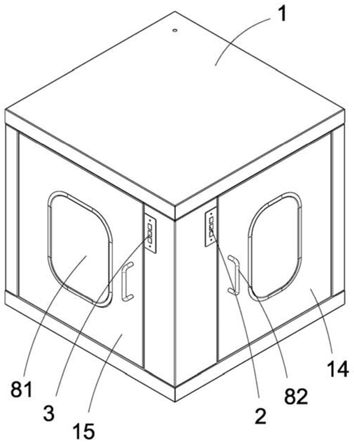 FIG. 1 - first structural schematic view of the three-door electronic-interlocking pass-through box
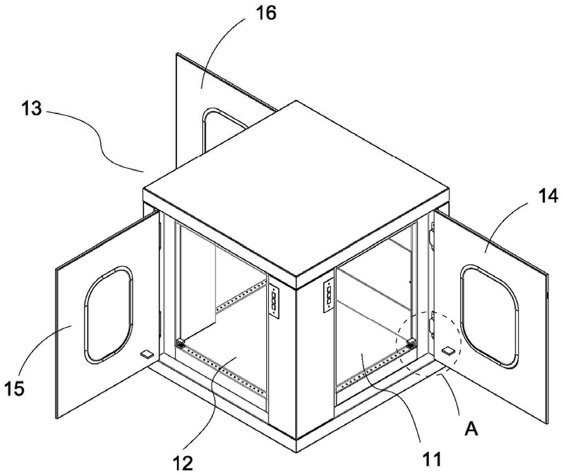 FIG. 2 - second structural schematic view of the three-door electronic-interlocking pass-through box
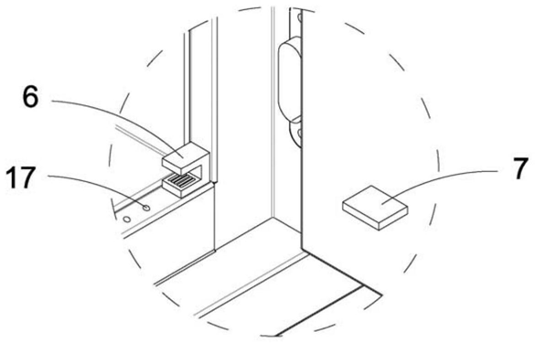 FIG. 3 - enlarged view of part A in FIG. 2
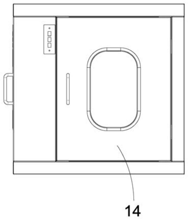 FIG. 4 - front view of the three-door electronic-interlocking pass-through box
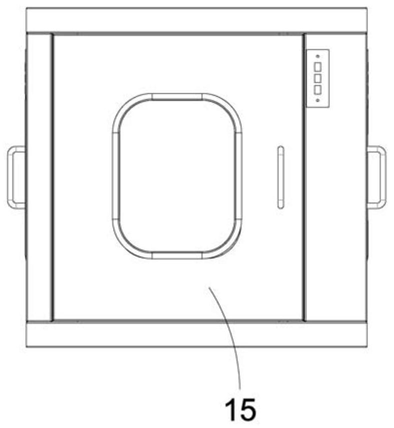 FIG. 5 - right side view of the three-door electronic-interlocking pass-through box
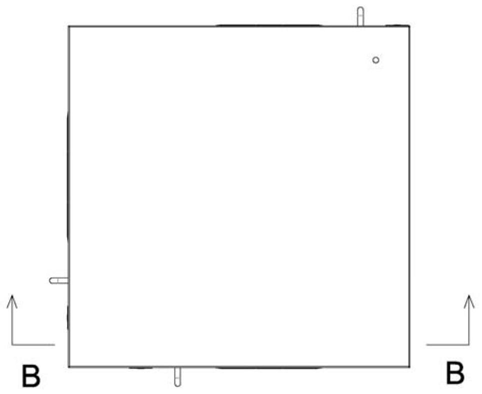 FIG. 6 - top view of the three-door electronic-interlocking pass-through box
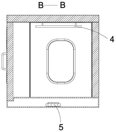 FIG. 7 - cross-sectional view taken along plane B-B in FIG. 6