A Clean Bench (Utility Model CN 210752786 U)
The present utility model provides a clean bench, comprising a workbench. The workbench comprises an air-extraction zone, an operation zone and a knee-control zone. A first drive assembly...
Abstract
The present utility model provides a clean bench, comprising a workbench. The workbench comprises an air-extraction zone, an operation zone and a knee-control zone. A first drive assembly is further fixed at a top end of the air-extraction zone, an output end of the first drive assembly is connected with a glass front cover panel, and a lower end of the glass front cover panel extends into the operation zone. The operation zone comprises a first zone, a second zone and a third zone, a first glass partition is provided between the first zone and the second zone, and a second glass partition is provided between the second zone and the third zone. The present utility model provides a clean bench in which the operation zone is divided into three zones, and every two zones are separated by a glass partition capable of moving up and down. Under the control of the knee-control assemblies, the operation zone can be transformed into one, two or three independent spaces, so that multiple experiments can be performed simultaneously and independently of one another.
Patent Information
| Item | Detail |
|---|---|
| Issuing authority | National Intellectual Property Administration of the People’s Republic of China (CNIPA) |
| Document type | Utility Model Patent |
| Authorization publication number | CN 210752786 U |
| Authorization publication date | June 16, 2020 |
| Application number | 201920992507.8 |
| Filing date | June 28, 2019 |
| Patentee | Dongguan Pengchi Purification Technology Co., Ltd. |
| Address | Tangyilangwei Road, Tangjiao Village, Chashan Town, Dongguan City, Guangdong Province 523378, China |
| Inventors | Hu Guopeng |
| Patent agency | Dongguan Yongqiao Intellectual Property Agency (General Partnership) 44400 |
| Patent agent | He Xinhua |
| International Patent Classification (IPC) | B01L 9/02 (2006.01) |
| Title of utility model | A Clean Bench |
Claims
-
A clean bench, characterized by comprising a workbench, the workbench comprising an air-extraction zone (1), an operation zone (2) and a knee-control zone (3);
- an exhaust outlet (11) is provided at a top end of the air-extraction zone (1), a fan (12) is provided at a lower side of the exhaust outlet (11), a breathable reflection plate (13) is fixed at a lower side of the fan (12), one end of the breathable reflection plate (13) is connected with a side plate (14), and a light source (15) is fixed on the side plate (14);
- a first drive assembly (16) is further fixed at the top end of the air-extraction zone (1), an output end of the first drive assembly (16) is connected with a glass front cover panel (17), and a lower end of the glass front cover panel (17) extends into the operation zone (2);
- the operation zone (2) comprises a first zone (21), a second zone (22) and a third zone (23), a first glass partition (24) is provided between the first zone (21) and the second zone (22), and a second glass partition (25) is provided between the second zone (22) and the third zone (23);
- a second drive assembly (31) is further connected to a lower end of the first glass partition (24), a third drive assembly is further connected to a lower end of the second glass partition (25), and the second drive assembly (31) and the third drive assembly are both located in the knee-control zone (3);
- a first knee-control assembly (32) and a second knee-control assembly (33) are further provided on the workbench, the first knee-control assembly (32) is electrically connected to the second drive assembly (31), and the second knee-control assembly (33) is electrically connected to the third drive assembly.
-
The clean bench according to claim 1, characterized in that the breathable reflection plate (13) is provided with a first breathable zone (131), a second breathable zone (132) and a third breathable zone (133) corresponding to the first zone (21), the second zone (22) and the third zone (23), respectively, and a plurality of breathable holes (134) are provided on each of the first breathable zone (131), the second breathable zone (132) and the third breathable zone (133);
- the breathable holes (134) are truncated-cone-shaped through holes, and both a lower surface of the breathable reflection plate (13) and inner side faces of the truncated-cone-shaped through holes are covered with a layer of reflective coating (135).
-
The clean bench according to claim 1, characterized in that the first drive assembly (16) comprises a first motor (161) fixed at the top end of the air-extraction zone (1), a first lead screw (162) connected to an output shaft of the first motor (161), and a first slider (163) slidably connected to the first lead screw (162), and the first slider (163) is fixedly connected to the glass front cover panel (17).
-
The clean bench according to claim 1, characterized in that the second drive assembly (31) comprises a second motor (311) fixed at the bottom of the knee-control zone (3), a second lead screw (312) connected to an output shaft of the second motor (311), and a second slider (313) slidably connected to the second lead screw (312), and the second slider (313) is fixedly connected to the first glass partition (24).
-
The clean bench according to claim 1, characterized in that the third drive assembly comprises a third motor fixed at the bottom of the knee-control zone (3), a third lead screw connected to an output shaft of the third motor, and a third slider slidably connected to the third lead screw, and the third slider is fixedly connected to the second glass partition (25).
-
The clean bench according to claim 1, characterized in that the first knee-control assembly (32) comprises a first pressure plate (321) and a second pressure plate (322) whose bottom portions are rotationally connected to the workbench, a first spring and a first switch located at an inner side of the first pressure plate (321), and a second spring (323) and a second switch (324) located at an inner side of the second pressure plate (322).
-
The clean bench according to claim 1, characterized in that the second knee-control assembly (33) comprises a third pressure plate (331) and a fourth pressure plate (332) whose bottom portions are rotationally connected to the workbench, a third spring and a third switch located at an inner side of the third pressure plate (331), and a fourth spring and a fourth switch located at an inner side of the fourth pressure plate (332).
-
The clean bench according to claim 1, characterized in that a cover switch (4) is further provided on the workbench, the cover switch (4) is located at one side of the air-extraction zone (1), and the cover switch (4) is electrically connected to the first drive assembly (16).
-
The clean bench according to claim 1, characterized in that a light source switch (5) electrically connected to the light source (15) and a fan switch (6) electrically connected to the fan (12) are further provided on the workbench.
Description
TECHNICAL FIELD
[0001] The present utility model relates to the technical field of purification equipment, and in particular to a clean bench.
BACKGROUND ART
[0002] The clean bench is a highly versatile purification device, widely used in scientific research and production departments requiring a locally clean and aseptic working environment, such as medicine and health, biopharmaceuticals, food, medical scientific experiments, optics, electronics, aseptic room experiments, aseptic microbiological testing, and plant tissue culture inoculation. The clean bench can be connected to a production line and has the advantages of low noise and movability, and it has good effects on improving process conditions, improving product quality and increasing the yield of finished products. Most clean benches in the prior art adopt an open tabletop, so that odors or toxic gases generated during internal operations easily diffuse into the room, or external air enters the operation zone and affects the experimental effects and the accuracy of results.
SUMMARY OF THE UTILITY MODEL
[0003] In view of the above problems, the present utility model provides a clean bench in which the operation zone is divided into three zones, and every two zones are separated by a glass partition capable of moving up and down. Under the control of the knee-control assemblies, the operation zone can be transformed into one, two or three independent spaces, so that multiple experiments can be performed simultaneously and independently of one another.
[0004] To achieve the above object, the present utility model solves the above problem through the following technical solutions:
[0005] A clean bench comprises a workbench. The workbench comprises an air-extraction zone, an operation zone and a knee-control zone. An exhaust outlet is provided at a top end of the air-extraction zone, a fan is provided at a lower side of the exhaust outlet, a breathable reflection plate is fixed at a lower side of the fan, one end of the breathable reflection plate is connected with a side plate, and a light source is fixed on the side plate. A first drive assembly is further fixed at the top end of the air-extraction zone, an output end of the first drive assembly is connected with a glass front cover panel, and a lower end of the glass front cover panel extends into the operation zone. The operation zone comprises a first zone, a second zone and a third zone, a first glass partition is provided between the first zone and the second zone, and a second glass partition is provided between the second zone and the third zone. A second drive assembly is further connected to a lower end of the first glass partition, a third drive assembly is further connected to a lower end of the second glass partition, and the second drive assembly and the third drive assembly are both located in the knee-control zone. A first knee-control assembly and a second knee-control assembly are further provided on the workbench, the first knee-control assembly is electrically connected to the second drive assembly, and the second knee-control assembly is electrically connected to the third drive assembly.
[0006] Specifically, the breathable reflection plate is provided with a first breathable zone, a second breathable zone and a third breathable zone corresponding to the first zone, the second zone and the third zone, respectively. A plurality of breathable holes are provided on each of the first breathable zone, the second breathable zone and the third breathable zone, the breathable holes are truncated-cone-shaped through holes, and both a lower surface of the breathable reflection plate and inner side faces of the truncated-cone-shaped through holes are covered with a layer of reflective coating.
[0007] Specifically, the first drive assembly comprises a first motor fixed at the top end of the air-extraction zone, a first lead screw connected to an output shaft of the first motor, and a first slider slidably connected to the first lead screw, and the first slider is fixedly connected to the glass front cover panel.
[0008] Specifically, the second drive assembly comprises a second motor fixed at the bottom of the knee-control zone, a second lead screw connected to an output shaft of the second motor, and a second slider slidably connected to the second lead screw, and the second slider is fixedly connected to the first glass partition.
[0009] Specifically, the third drive assembly comprises a third motor fixed at the bottom of the knee-control zone, a third lead screw connected to an output shaft of the third motor, and a third slider slidably connected to the third lead screw, and the third slider is fixedly connected to the second glass partition.
[0010] Specifically, the first knee-control assembly comprises a first pressure plate and a second pressure plate whose bottom portions are rotationally connected to the workbench, a first spring and a first switch located at an inner side of the first pressure plate, and a second spring and a second switch located at an inner side of the second pressure plate.
[0011] Specifically, the second knee-control assembly comprises a third pressure plate and a fourth pressure plate whose bottom portions are rotationally connected to the workbench, a third spring and a third switch located at an inner side of the third pressure plate, and a fourth spring and a fourth switch located at an inner side of the fourth pressure plate.
[0012] Specifically, a cover switch is further provided on the workbench, the cover switch is located at one side of the air-extraction zone, and the cover switch is electrically connected to the first drive assembly.
[0013] Specifically, a light source switch electrically connected to the light source and a fan switch electrically connected to the fan are further provided on the workbench.
[0014] The beneficial effects of the present utility model are as follows:
[0015] First, in the clean bench of the present utility model, the operation zone is divided into three zones, and every two zones are separated by a glass partition capable of moving up and down. Under the control of the knee-control assemblies, the operation zone can be transformed into one, two or three independent spaces, so that multiple experiments can be performed simultaneously and independently of one another;
[0016] Second, a raisable and lowerable glass front cover panel is added. By lowering the height of the glass front cover panel, the gas in the operation zone is prevented from diffusing into the room, and the accuracy of experimental results is improved;
[0017] Third, the light source is arranged on the side plate, and both the lower surface of the breathable reflection plate and the inner side faces of the truncated-cone-shaped through holes are covered with a layer of reflective coating. Light emitted by the light source can be reflected by the reflective coating to illuminate the operation zone, avoiding the problem of glare caused by direct light in a conventional arrangement in which the light source is provided on an inner side face of the operation zone.
BRIEF DESCRIPTION OF THE DRAWINGS
[0018] FIG. 1 is a front view of a clean bench according to the present utility model.
[0019] FIG. 2 is a cross-sectional view taken along plane A-A in FIG. 1.
[0020] FIG. 3 is an enlarged view of part B in FIG. 2.
[0021] FIG. 4 is structural schematic view I of the breathable reflection plate in the present utility model.
[0022] FIG. 5 is structural schematic view II of the breathable reflection plate in the present utility model.
[0023] FIG. 6 is an enlarged view of part C in FIG. 5.
[0024] The reference numerals are as follows: air-extraction zone 1; exhaust outlet 11; fan 12; breathable reflection plate 13; first breathable zone 131; second breathable zone 132; third breathable zone 133; breathable holes 134; reflective coating 135; side plate 14; light source 15; first drive assembly 16; first motor 161; first lead screw 162; first slider 163; glass front cover panel 17; operation zone 2; first zone 21; second zone 22; third zone 23; first glass partition 24; second glass partition 25; knee-control zone 3; second drive assembly 31; second motor 311; second lead screw 312; second slider 313; first knee-control assembly 32; first pressure plate 321; second pressure plate 322; second spring 323; second switch 324; second knee-control assembly 33; third pressure plate 331; fourth pressure plate 332; cover switch 4; light source switch 5; fan switch 6.
DETAILED DESCRIPTION OF EMBODIMENTS
[0025] The present utility model will be described in further detail below in conjunction with the embodiments and the accompanying drawings, but the embodiments of the present utility model are not limited thereto.
[0026] As shown in FIGS. 1-6:
[0027] A clean bench comprises a workbench. The workbench comprises an air-extraction zone 1, an operation zone 2 and a knee-control zone 3. An exhaust outlet 11 is provided at a top end of the air-extraction zone 1, a fan 12 is provided at a lower side of the exhaust outlet 11, a breathable reflection plate 13 is fixed at a lower side of the fan 12, one end of the breathable reflection plate 13 is connected with a side plate 14, and a light source 15 is fixed on the side plate 14. A first drive assembly 16 is further fixed at the top end of the air-extraction zone 1, an output end of the first drive assembly 16 is connected with a glass front cover panel 17, and a lower end of the glass front cover panel 17 extends into the operation zone 2. The operation zone 2 comprises a first zone 21, a second zone 22 and a third zone 23, a first glass partition 24 is provided between the first zone 21 and the second zone 22, and a second glass partition 25 is provided between the second zone 22 and the third zone 23. A second drive assembly 31 is further connected to a lower end of the first glass partition 24, and up-and-down movement of the first glass partition 24 can be controlled by means of the second drive assembly 31. A third drive assembly is further connected to a lower end of the second glass partition 25, and up-and-down movement of the second glass partition 25 can be controlled by means of the third drive assembly. When the first glass partition 24 and the second glass partition 25 are raised, the operation zone 2 can be divided into three zones; when any one of the first glass partition 24 and the second glass partition 25 is raised, the operation zone 2 can be divided into two zones. The second drive assembly 31 and the third drive assembly are both located in the knee-control zone 3. A first knee-control assembly 32 and a second knee-control assembly 33 are further provided on the workbench. The first knee-control assembly 32 is electrically connected to the second drive assembly 31, and the first knee-control assembly 32 is used for actuating the second drive assembly 31; the second knee-control assembly 33 is electrically connected to the third drive assembly, and the second knee-control assembly 33 is used for controlling the actuation of the third drive assembly.
[0028] Preferably, the breathable reflection plate 13 is provided with a first breathable zone 131, a second breathable zone 132 and a third breathable zone 133 corresponding to the first zone 21, the second zone 22 and the third zone 23, respectively. A plurality of breathable holes 134 are provided on each of the first breathable zone 131, the second breathable zone 132 and the third breathable zone 133, the breathable holes 134 are truncated-cone-shaped through holes, and both a lower surface of the breathable reflection plate 13 and inner side faces of the truncated-cone-shaped through holes are covered with a layer of reflective coating 135. Light emitted by the light source 15 can be reflected by the reflective coating 135 to illuminate the operation zone 2, avoiding the problem of glare caused by direct light in a conventional arrangement in which the light source is provided on an inner side face of the operation zone.
[0029] Preferably, the first drive assembly 16 comprises a first motor 161 fixed at the top end of the air-extraction zone 1, a first lead screw 162 connected to an output shaft of the first motor 161, and a first slider 163 slidably connected to the first lead screw 162, and the first slider 163 is fixedly connected to the glass front cover panel 17.
[0030] Preferably, the second drive assembly 31 comprises a second motor 311 fixed at the bottom of the knee-control zone 3, a second lead screw 312 connected to an output shaft of the second motor 311, and a second slider 313 slidably connected to the second lead screw 312, and the second slider 313 is fixedly connected to the first glass partition 24.
[0031] Preferably, the third drive assembly comprises a third motor fixed at the bottom of the knee-control zone 3, a third lead screw connected to an output shaft of the third motor, and a third slider slidably connected to the third lead screw, and the third slider is fixedly connected to the second glass partition 25.
[0032] Preferably, the first knee-control assembly 32 comprises a first pressure plate 321 and a second pressure plate 322 whose bottom portions are rotationally connected to the workbench, a first spring and a first switch located at an inner side of the first pressure plate 321, and a second spring 323 and a second switch 324 located at an inner side of the second pressure plate 322. When the first pressure plate 321 is pressed by a knee, a protrusion at the inner side of the first pressure plate 321 brings the first switch into contact and the circuit is energized; when the second pressure plate 322 is pressed by a knee, a protrusion at the inner side of the second pressure plate 322 brings the second switch into contact and the circuit is energized; the first spring and the second spring 323 provide the first pressure plate 321 and the second pressure plate 322 with a resetting function.
[0033] Preferably, the second knee-control assembly 33 comprises a third pressure plate 331 and a fourth pressure plate 332 whose bottom portions are rotationally connected to the workbench, a third spring and a third switch located at an inner side of the third pressure plate 331, and a fourth spring and a fourth switch located at an inner side of the fourth pressure plate 332.
[0034] Preferably, a cover switch 4 is further provided on the workbench, the cover switch 4 is located at one side of the air-extraction zone 1, and the cover switch 4 is electrically connected to the first drive assembly 16.
[0035] Preferably, a light source switch 5 electrically connected to the light source 15 and a fan switch 6 electrically connected to the fan 12 are further provided on the workbench.
[0036] The above embodiments only illustrate one embodiment of the present utility model, and the description thereof is relatively specific and detailed, but it should not be construed as limiting the patent scope of the present utility model. It should be noted that those of ordinary skill in the art may make various modifications and improvements without departing from the concept of the present utility model, and these all fall within the protection scope of the present utility model. Therefore, the patent protection scope of the present utility model shall be subject to the appended claims.
Drawings
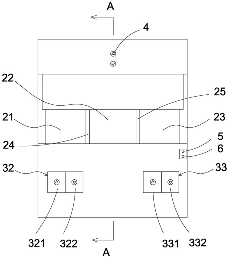 FIG. 1 — Front view of the clean bench
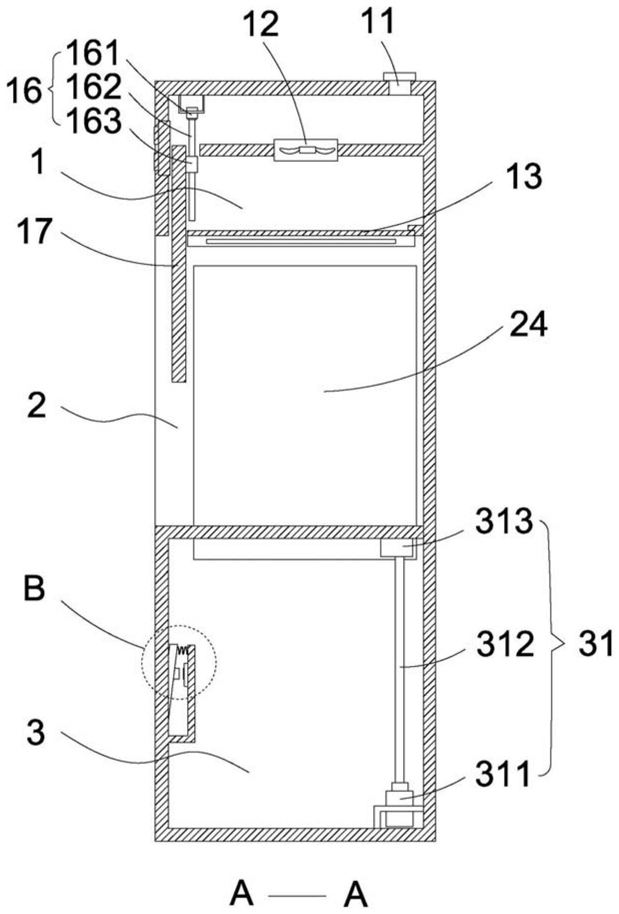 FIG. 2 — Cross-sectional view taken along plane A-A in FIG. 1
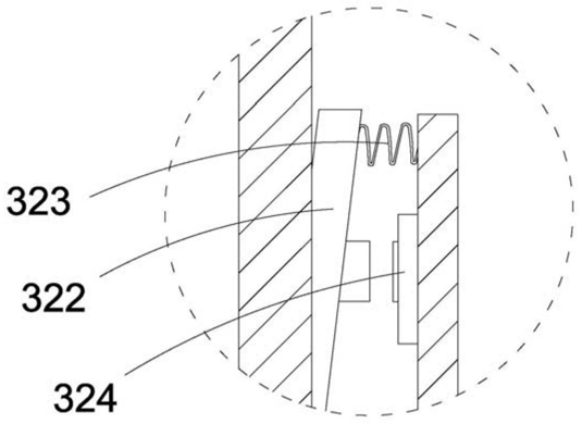 FIG. 3 — Enlarged view of part B in FIG. 2
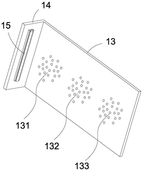 FIG. 4 — Structural schematic view I of the breathable reflection plate
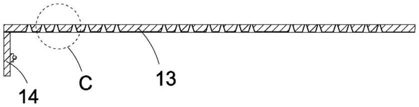 FIG. 5 — Structural schematic view II of the breathable reflection plate
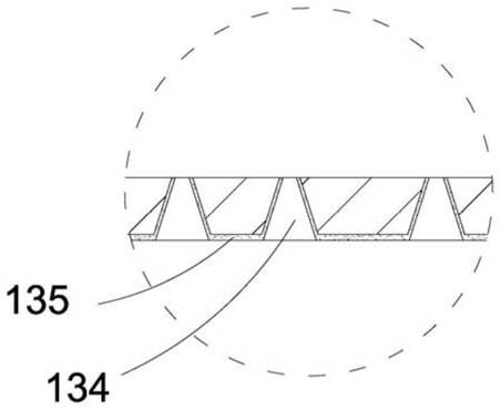 FIG. 6 — Enlarged view of part C in FIG. 5