An Edge-Trimmed Observation Window Structure (Utility Model CN 210317039 U)
The present utility model provides an edge-trimmed observation window structure. The inclined-surface side of a trim strip A abuts against the vertical-surface side of a trim strip D; the...
Abstract
The present utility model provides an edge-trimmed observation window structure. The inclined-surface side of a trim strip A abuts against the vertical-surface side of a trim strip D; the inclined-surface side of a trim strip B abuts against the vertical-surface side of the trim strip A; the inclined-surface side of a trim strip C abuts against the vertical-surface side of the trim strip B; and the inclined-surface side of the trim strip D abuts against the vertical-surface side of the trim strip C. The vertical-surface sides of the trim strip A, the trim strip B, the trim strip C, and the trim strip D all extend to the position of the U-shaped plate body on the adjacent side. When a gap is formed between the vertical-surface side of the trim strip A and the inclined-surface side of the trim strip B, since the length of the trim strip B is greater than the side length of the glass, the trim strip B can be moved so that its inclined surface remains in abutment against the trim strip A, while the vertical-surface side of the trim strip B is covered by the inclined-surface side of the trim strip C, thereby ensuring that no gap appears. By analogy, with this structural arrangement, the machining accuracy requirement for the trim strips is reduced, and the production efficiency is also improved.
Patent Information
| Item | Detail |
|---|---|
| Issuing authority | National Intellectual Property Administration of the People’s Republic of China (CNIPA) |
| Document type | Utility Model Patent |
| Authorization publication number | CN 210317039 U |
| Authorization publication date | 2020-04-14 |
| Application number | 201920808599.X |
| Filing date | 2019-05-31 |
| Patentee | Dongguan Pengchi Purification Technology Co., Ltd. |
| Address | Tangyilangwei Road, Tangjiao Village, Chashan Town, Dongguan City, Guangdong Province 523378, China |
| Inventors | Wang Haiou; Hu Guopeng; Li Dexiong |
| Patent agency | Dongguan Yongqiao Intellectual Property Agency (General Partnership) 44400 |
| Patent agent | He Xinhua |
| International Patent Classification (IPC) | E06B 3/58(2006.01); E06B 7/30(2006.01) |
| Title of utility model | An Edge-Trimmed Observation Window Structure |
Claims
-
An edge-trimmed observation window structure, comprising a limiting frame, glass (10), and a positioning structure, characterized in that:
- the limiting frame comprises four U-shaped plate bodies (14) corresponding to outer edges of the glass (10);
- the positioning structure is enclosed by four profiled plate bodies (13) and a trim strip A (12), a trim strip B (11), a trim strip C (16), and a trim strip D (15) respectively corresponding to the profiled plate bodies (13);
- each profiled plate body (13) comprises an extension section A (23), a connecting section (21), and an extension section B (24);
- the connecting section (21) connects the extension section A (23) and the extension section B (24) into one body;
- the extension section A (23) is perpendicular to the connecting section (21), and an acute angle is formed between the connecting section (21) and the extension section B (24);
- a bent section (18) is disposed at one end of each of the trim strip A (12), the trim strip B (11), the trim strip C (16), and the trim strip D (15);
- one end of each of the trim strip A (12), the trim strip B (11), the trim strip C (16), and the trim strip D (15) along its length direction is configured as a vertical surface (20), and the other end along its length direction is configured as a 45-degree inclined surface (22);
- the trim strip A (12), the trim strip B (11), the trim strip C (16), and the trim strip D (15) are correspondingly disposed on a side of the profiled plate body (13) facing the extension section A (23);
- the bent section (18) is perpendicular to the extension section A (23), so as to form a clamping groove (17);
- four side surfaces of the glass (10) are inserted into the corresponding clamping grooves (17);
- one side surface of the connecting section (21) is in close contact with one side surface of the U-shaped plate body (14);
- the inclined-surface (22) side of the trim strip A (12) abuts against the vertical-surface (20) side of the trim strip D (15);
- the inclined-surface (22) side of the trim strip B (11) abuts against the vertical-surface (20) side of the trim strip A (12);
- the inclined-surface (22) side of the trim strip C (16) abuts against the vertical-surface (20) side of the trim strip B (11);
- the inclined-surface (22) side of the trim strip D (15) abuts against the vertical-surface (20) side of the trim strip C (16);
- the vertical-surface (20) sides of the trim strip A (12), the trim strip B (11), the trim strip C (16), and the trim strip D (15) all extend to the position of the U-shaped plate body (14) on the adjacent side; and
- the lengths of the trim strip A (12), the trim strip B (11), the trim strip C (16), and the trim strip D (15) are all greater than a side length of the glass (10).
-
The edge-trimmed observation window structure according to claim 1, characterized in that each profiled plate body (13) is fixed to the U-shaped plate body (14) by a bolt.
-
The edge-trimmed observation window structure according to claim 1, characterized in that a bending angle of each bent section (18) is 45 degrees.
-
The edge-trimmed observation window structure according to claim 1, characterized in that a bending surface of each bent section (18) is configured as an arc-shaped surface (19).
-
The edge-trimmed observation window structure according to claim 1, characterized in that a joint between the connecting section (21) and the extension section B (24) is configured as an arc-shaped surface (19).
Description
TECHNICAL FIELD
[0001] The present utility model relates to the technical field of observation window processing, and in particular to an edge-trimmed observation window structure.
BACKGROUND ART
[0002] An observation window is a window used for observing the test condition of a sample in a working space. An observation window applied on a door is generally provided with trim strips around the four sides of glass, on the one hand to cooperate with a fixing structure to position the glass, and on the other hand to make the observation window aesthetically pleasing. In the prior art, this type of observation window generally has the following defects: 1. The trim strips are either configured in a trapezoidal structure (as shown in FIG. 1) or in a rectangular structure (as shown in FIG. 2), and are then sequentially enclosed by four trim strips. The defect common to both structures is that very high accuracy in the length and width of the trim strips is required. Once there is a difference in length or width between two adjacent trim strips, a gap will appear, and one either accepts this situation that affects the aesthetic appearance, or re-matches trim strips with exactly the same length and width, which increases the rejection rate. In order to reduce errors, efficiency must be reduced, which is not the best approach for the long-term development of an enterprise. 2. The trim strips are each simply a strip-shaped block, and their edge positions are generally rough surfaces that have not been polished, which can easily scrape hands and poses a safety hazard. In view of the above, an observation window structure capable of solving the above problems is urgently needed.
SUMMARY OF THE UTILITY MODEL
[0003] Based on the above, an object of the present utility model is to provide an edge-trimmed observation window structure. By adjusting the structure of the trim strips, on the premise of ensuring the aesthetic appearance, the occurrence of gaps is eliminated, the product quality is ensured, and the production efficiency is also improved. The trim strips of the improved structure also effectively avoid rough surfaces and solve the safety hazard problem of easily scraping hands.
[0004] The present utility model provides an edge-trimmed observation window structure, comprising a limiting frame, glass, and a positioning structure. The limiting frame comprises four U-shaped plate bodies corresponding to outer edges of the glass. The positioning structure is enclosed by four profiled plate bodies and a trim strip A, a trim strip B, a trim strip C, and a trim strip D respectively corresponding to the profiled plate bodies. Each profiled plate body comprises an extension section A, a connecting section, and an extension section B. The connecting section connects the extension section A and the extension section B into one body. The extension section A is perpendicular to the connecting section, and an acute angle is formed between the connecting section and the extension section B. A bent section is disposed at one end of each of the trim strip A, the trim strip B, the trim strip C, and the trim strip D. One end of each of the trim strip A, the trim strip B, the trim strip C, and the trim strip D along its length direction is configured as a vertical surface, and the other end along its length direction is configured as a 45-degree inclined surface. The trim strip A, the trim strip B, the trim strip C, and the trim strip D are correspondingly disposed on a side of the profiled plate body facing the extension section A. The bent section is perpendicular to the extension section A, so as to form a clamping groove. Four side surfaces of the glass are inserted into the corresponding clamping grooves, and one side surface of the connecting section is in close contact with one side surface of the U-shaped plate body. The inclined-surface side of the trim strip A abuts against the vertical-surface side of the trim strip D; the inclined-surface side of the trim strip B abuts against the vertical-surface side of the trim strip A; the inclined-surface side of the trim strip C abuts against the vertical-surface side of the trim strip B; and the inclined-surface side of the trim strip D abuts against the vertical-surface side of the trim strip C. The vertical-surface sides of the trim strip A, the trim strip B, the trim strip C, and the trim strip D all extend to the position of the U-shaped plate body on the adjacent side, and the lengths of the trim strip A, the trim strip B, the trim strip C, and the trim strip D are all greater than a side length of the glass.
[0005] As a preferred solution, each profiled plate body is fixed to the U-shaped plate body by a bolt.
[0006] As a preferred solution, the bending angle of each bent section is 45 degrees.
[0007] As a preferred solution, the bending surface of each bent section is configured as an arc-shaped surface.
[0008] As a preferred solution, the joint between the connecting section and the extension section B is configured as an arc-shaped surface.
[0009] The present utility model has the following beneficial effects: the inclined-surface side of the trim strip A abuts against the vertical-surface side of the trim strip D; the inclined-surface side of the trim strip B abuts against the vertical-surface side of the trim strip A; the inclined-surface side of the trim strip C abuts against the vertical-surface side of the trim strip B; and the inclined-surface side of the trim strip D abuts against the vertical-surface side of the trim strip C. The vertical-surface sides of the trim strip A, the trim strip B, the trim strip C, and the trim strip D all extend to the position of the U-shaped plate body on the adjacent side, and the lengths of the trim strip A, the trim strip B, the trim strip C, and the trim strip D are all greater than the side length of the glass. When a gap is formed between the vertical-surface side of the trim strip A and the inclined-surface side of the trim strip B, since the length of the trim strip B is greater than the side length of the glass, the trim strip B can be moved so that its inclined surface remains in abutment against the trim strip A, while the vertical-surface side of the trim strip B is covered by the inclined-surface side of the trim strip C, thereby ensuring that no gap appears. By analogy, if gaps exist between adjacent ones of the trim strip B, the trim strip C, and the trim strip D, they can all be adjusted in this manner. With this structural arrangement, the machining accuracy requirement for the trim strip A, the trim strip B, the trim strip C, and the trim strip D is reduced, the product quality is ensured, and the production efficiency is also improved. A bent section is disposed at one end of each of the trim strip A, the trim strip B, the trim strip C, and the trim strip D, and the trim strip A, the trim strip B, the trim strip C, and the trim strip D are an integrally formed structure without rough surfaces, thereby solving the safety hazard problem of easily scraping hands.
BRIEF DESCRIPTION OF THE DRAWINGS
[0010] FIG. 1 is a schematic view of trapezoidal trim strips in the prior art.
[0011] FIG. 2 is a schematic view of rectangular trim strips in the prior art.
[0012] FIG. 3 is an exploded structural view of the present utility model.
[0013] FIG. 4 is a front exploded view showing the structural relationship of the trim strip A, the trim strip B, the trim strip C, the trim strip D, and the glass.
[0014] FIG. 5 is a cross-sectional view of the present utility model.
[0015] FIG. 6 is an enlarged view of position A in FIG. 5.
[0016] FIG. 7 is a front view of the present utility model.
[0017] FIG. 8 is a perspective view of the present utility model in a use state.
[0018] The reference numerals are as follows: glass (10), trim strip A (12), trim strip B (11), trim strip C (16), trim strip D (15), U-shaped plate body (14), profiled plate body (13), clamping groove (17), bent section (18), arc-shaped surface (19), vertical surface (20), inclined surface (22), extension section A (23), connecting section (21), and extension section B (24).
DETAILED DESCRIPTION OF EMBODIMENTS
[0019] In order to further understand the features, technical means, and specific objects and functions achieved by the present utility model, the present utility model is described in further detail below with reference to the accompanying drawings and specific embodiments.
[0020] Referring to FIGS. 3-8, an edge-trimmed observation window structure comprises a limiting frame, glass (10), and a positioning structure. The limiting frame comprises four U-shaped plate bodies (14) corresponding to the outer edges of the glass (10). The positioning structure is enclosed by four profiled plate bodies (13) and a trim strip A (12), a trim strip B (11), a trim strip C (16), and a trim strip D (15) respectively corresponding to the profiled plate bodies (13). Each profiled plate body (13) is fixed to the U-shaped plate body (14) by a bolt.
[0021] Each profiled plate body (13) comprises an extension section A (23), a connecting section (21), and an extension section B (24). The connecting section (21) connects the extension section A (23) and the extension section B (24) into one body. The extension section A (23) is perpendicular to the connecting section (21), and an acute angle is formed between the connecting section (21) and the extension section B (24). A bent section (18) is disposed at one end of each of the trim strip A (12), the trim strip B (11), the trim strip C (16), and the trim strip D (15), and a bending angle of each bent section (18) is 45 degrees. One end of each of the trim strip A (12), the trim strip B (11), the trim strip C (16), and the trim strip D (15) along its length direction is configured as a vertical surface (20), and the other end along its length direction is configured as a 45-degree inclined surface (22). The trim strip A (12), the trim strip B (11), the trim strip C (16), and the trim strip D (15) are correspondingly disposed on a side of the profiled plate body (13) facing the extension section A (23). The bent section (18) is perpendicular to the extension section A (23), so as to form a clamping groove (17). Four side surfaces of the glass (10) are inserted into the corresponding clamping grooves (17), and one side surface of the connecting section (21) is in close contact with one side surface of the U-shaped plate body (14). The clamping grooves (17) further fix the glass and each trim strip by adhesive.
[0022] The inclined-surface (22) side of the trim strip A (12) abuts against the vertical-surface (20) side of the trim strip D (15); the inclined-surface (22) side of the trim strip B (11) abuts against the vertical-surface (20) side of the trim strip A (12); the inclined-surface (22) side of the trim strip C (16) abuts against the vertical-surface (20) side of the trim strip B (11); and the inclined-surface (22) side of the trim strip D (15) abuts against the vertical-surface (20) side of the trim strip C (16). The vertical-surface (20) sides of the trim strip A (12), the trim strip B (11), the trim strip C (16), and the trim strip D (15) all extend to the position of the U-shaped plate body (14) on the adjacent side. The lengths of the trim strip A (12), the trim strip B (11), the trim strip C (16), and the trim strip D (15) are all greater than the side length of the glass (10).
[0023] The bending surface of each bent section (18) is configured as an arc-shaped surface (19), and the joint between the connecting section (21) and the extension section B (24) is configured as an arc-shaped surface (19), so as to further enhance the smoothness of both end surfaces at the opening of the clamping groove (17). On the one hand, this makes the product more aesthetically pleasing; on the other hand, it further improves the safety factor of the product and avoids the situation of scraping hands.
[0024] In this embodiment, the inclined-surface side of the trim strip A abuts against the vertical-surface side of the trim strip D; the inclined-surface side of the trim strip B abuts against the vertical-surface side of the trim strip A; the inclined-surface side of the trim strip C abuts against the vertical-surface side of the trim strip B; and the inclined-surface side of the trim strip D abuts against the vertical-surface side of the trim strip C. The vertical-surface sides of the trim strip A, the trim strip B, the trim strip C, and the trim strip D all extend to the position of the U-shaped plate body on the adjacent side, and the lengths of the trim strip A, the trim strip B, the trim strip C, and the trim strip D are all greater than the side length of the glass. When a gap is formed between the vertical-surface side of the trim strip A and the inclined-surface side of the trim strip B, since the length of the trim strip B is greater than the side length of the glass, the trim strip B can be moved so that its inclined surface remains in abutment against the trim strip A, while the vertical-surface side of the trim strip B is covered by the inclined-surface side of the trim strip C, thereby ensuring that no gap appears. By analogy, if gaps exist between adjacent ones of the trim strip B, the trim strip C, and the trim strip D, they can all be adjusted in this manner. With this structural arrangement, the machining accuracy requirement for the trim strip A, the trim strip B, the trim strip C, and the trim strip D is reduced, the product quality is ensured, and the production efficiency is also improved. A bent section is disposed at one end of each of the trim strip A, the trim strip B, the trim strip C, and the trim strip D, and the trim strip A, the trim strip B, the trim strip C, and the trim strip D are an integrally formed structure without rough surfaces, thereby solving the safety hazard problem of easily scraping hands.
[0025] The above embodiments only describe one embodiment of the present utility model, and the description thereof is relatively specific and detailed. However, this should not be construed as a limitation on the patent scope of the present utility model. It should be noted that, for a person of ordinary skill in the art, without departing from the concept of the present utility model, several modifications and improvements can be made, all of which fall within the protection scope of the present utility model. Therefore, the protection scope of the present utility model patent shall be defined by the appended claims.
Drawings
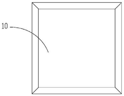 FIG. 1 — Schematic view of trapezoidal trim strips in the prior art
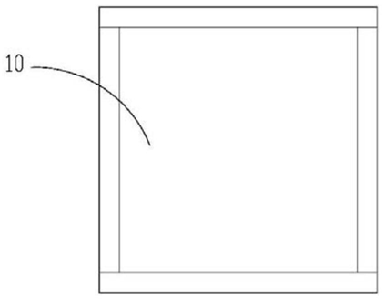 FIG. 2 — Schematic view of rectangular trim strips in the prior art
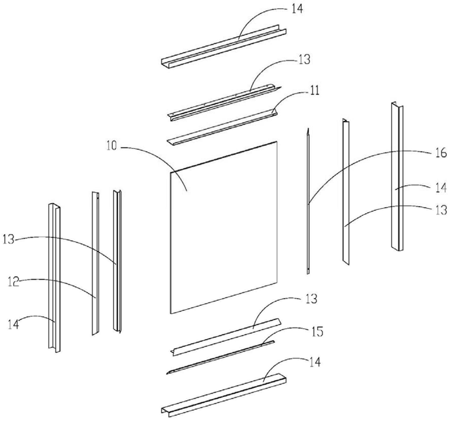 FIG. 3 — Exploded structural view of the present utility model
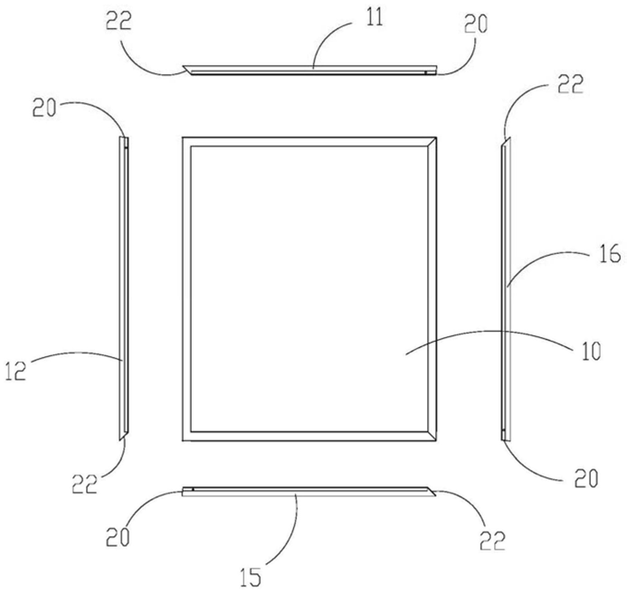 FIG. 4 — Front exploded view of the structural relationship of trim strips A-D and the glass
 FIG. 5 — Cross-sectional view of the present utility model
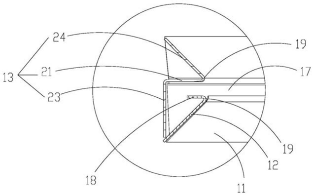 FIG. 6 — Enlarged view of position A in FIG. 5
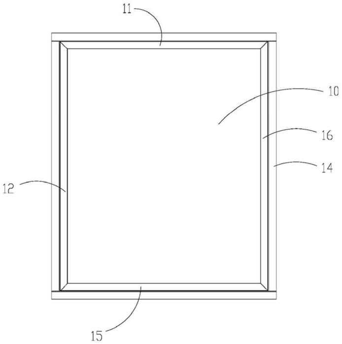 FIG. 7 — Front view of the present utility model
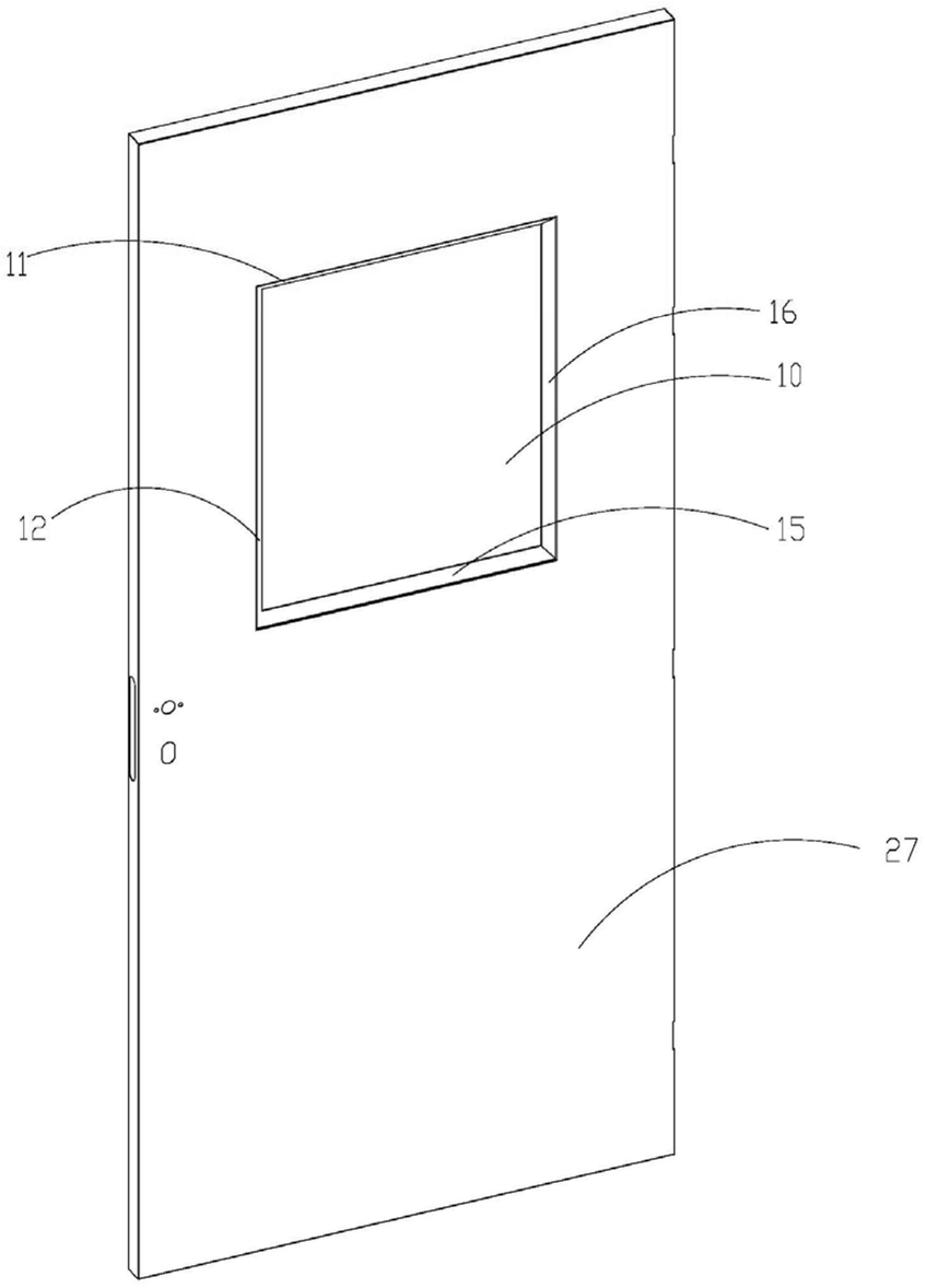 FIG. 8 — Perspective view of the present utility model in a use state