A Medical Imaging X-ray Film Viewer (Illuminator) (Utility Model CN 210051967 U)
The present utility model provides a medical imaging X-ray film viewer (illuminator), comprising a lamp box and a box cover covering an upper end of the lamp box, wherein a cavity is formed...
Abstract
The present utility model provides a medical imaging X-ray film viewer (illuminator), comprising a lamp box and a box cover covering an upper end of the lamp box, wherein a cavity is formed in the lamp box; a plurality of lamp tubes are disposed in the cavity; the box cover comprises an outer frame, an inner frame and a light-transmitting plate fixed to an inner side of the inner frame; the outer frame is fixed to an edge of the upper end of the lamp box; one end of the inner frame is rotationally connected to the lamp box, and the other end is fixedly connected to the lamp box; an upper pivot and a lower pivot are disposed at the rotational connection between the inner frame and the lamp box; a spring is sleeved outside the upper pivot; and a plurality of magnetic attraction discs are disposed on the light-transmitting plate. The medical imaging X-ray film viewer (illuminator) of the present utility model is simple in structure, has a good film viewing effect, and allows an X-ray film to be installed conveniently and not easily damaged.
Patent Information
| Item | Detail |
|---|---|
| Issuing authority | National Intellectual Property Administration of the People’s Republic of China (CNIPA) |
| Document type | Utility Model Patent |
| Authorization publication number | CN 210051967 U |
| Authorization publication date | 11.02.2020 |
| Application number | 201920806854.7 |
| Filing date | 31.05.2019 |
| Patentee | Dongguan Pengchi Purification Technology Co., Ltd. |
| Address | Tangyilangwei Road, Tangjiao Village, Chashan Town, Dongguan City, Guangdong Province 523378, China |
| Inventors | Wang Haiou; Hu Guopeng; Li Dexiong |
| Patent agency | Dongguan Yongqiao Intellectual Property Agency (General Partnership) 44400 |
| Patent agent | He Xinhua |
| International Patent Classification (IPC) | G02B 27/02(2006.01) |
| Title of utility model | A Medical Imaging X-ray Film Viewer (Illuminator) |
Claims
-
A medical imaging X-ray film viewer (illuminator), comprising a lamp box (1) and a box cover (2) covering an upper end of the lamp box (1), wherein a cavity (11) is formed in the lamp box (1), and a plurality of lamp tubes (12) are disposed in the cavity (11), characterized in that:
- the box cover (2) comprises an outer frame (21), an inner frame (22) and a light-transmitting plate (23) fixed to an inner side of the inner frame (22);
- the outer frame (21) is fixed to an edge of the upper end of the lamp box (1);
- one end of the inner frame (22) is rotationally connected to the lamp box (1), and the other end is fixedly connected to the lamp box (1);
- an upper pivot (31) and a lower pivot (32) are disposed at the rotational connection between the inner frame (22) and the lamp box (1);
- a spring (33) is sleeved outside the upper pivot (31);
- a plurality of magnetic attraction discs (4) are disposed on the light-transmitting plate (23).
-
The medical imaging X-ray film viewer (illuminator) according to claim 1, characterized in that each magnetic attraction disc (4) comprises a mounting portion (41) in threaded connection with the light-transmitting plate (23) and a magnetic attraction portion (42) connected to one end of the mounting portion (41);
- the magnetic attraction portion (42) is disposed on a side away from the lamp box (1).
-
The medical imaging X-ray film viewer (illuminator) according to claim 2, characterized in that the magnetic attraction portion (42) is selected from one of iron-containing stainless steel, cobalt-containing stainless steel and nickel-containing stainless steel.
-
The medical imaging X-ray film viewer (illuminator) according to claim 1, characterized in that a switch indicator lamp (5) is further disposed on the light-transmitting plate (23).
-
The medical imaging X-ray film viewer (illuminator) according to claim 1, characterized in that two heat-conducting aluminum plates (13) are further fixed to the bottom of the cavity (11), and both heat-conducting aluminum plates (13) are located at a lower side of the lamp tubes (12).
-
The medical imaging X-ray film viewer (illuminator) according to claim 1, characterized in that the other end of the inner frame (22) is fixedly connected to the lamp box (1) through bolts.
Description
TECHNICAL FIELD
[0001] The present utility model relates to the field of medical equipment, and specifically relates to a medical imaging X-ray film viewer (illuminator).
BACKGROUND ART
[0002] An X-ray film viewer (illuminator) is a film viewing box developed for adapting to the observation of medical imaging photos; the film viewing box has a simple processing technology and can read X-ray films more quickly and conveniently, and is currently used relatively widely in middle- and high-grade hospitals and high-grade non-destructive testing institutions. In a traditional X-ray film viewer (illuminator), an X-ray film is clamped by means of a clamping gap between the box body and the light-transmitting plate, or clamped by means of clips, and such a clamping manner causes abrasion to the periphery of the X-ray film.
SUMMARY OF THE UTILITY MODEL
[0003] In view of the above problems, the present utility model provides a medical imaging X-ray film viewer (illuminator) which is simple in structure, has a good film viewing effect, and allows an X-ray film to be installed conveniently and not easily damaged.
[0004] To achieve the above objective, the present utility model solves the problems through the following technical solutions:
[0005] A medical imaging X-ray film viewer (illuminator) comprises a lamp box and a box cover covering an upper end of the lamp box, wherein a cavity is formed in the lamp box; a plurality of lamp tubes are disposed in the cavity; the box cover comprises an outer frame, an inner frame and a light-transmitting plate fixed to an inner side of the inner frame; the outer frame is fixed to an edge of the upper end of the lamp box; one end of the inner frame is rotationally connected to the lamp box, and the other end is fixedly connected to the lamp box; an upper pivot and a lower pivot are disposed at the rotational connection between the inner frame and the lamp box; a spring is sleeved outside the upper pivot; and a plurality of magnetic attraction discs are disposed on the light-transmitting plate.
[0006] Specifically, each magnetic attraction disc comprises a mounting portion in threaded connection with the light-transmitting plate and a magnetic attraction portion connected to one end of the mounting portion; and the magnetic attraction portion is disposed on a side away from the lamp box.
[0007] Specifically, the magnetic attraction portion is selected from one of iron-containing stainless steel, cobalt-containing stainless steel and nickel-containing stainless steel.
[0008] Specifically, a switch indicator lamp is further disposed on the light-transmitting plate.
[0009] Specifically, two heat-conducting aluminum plates are further fixed to the bottom of the cavity, and both heat-conducting aluminum plates are located at a lower side of the lamp tubes.
[0010] Specifically, the other end of the inner frame is fixedly connected to the lamp box through bolts.
[0011] The present utility model has the following beneficial effects:
[0012] First, the medical imaging X-ray film viewer (illuminator) of the present utility model is additionally provided with a plurality of magnetic attraction discs; an X-ray film can be placed on the light-transmitting plate, and then magnetic buttons are placed, and the X-ray film is fixed by means of the magnetic attraction between the magnetic buttons and the magnetic attraction discs, so that the installation is convenient and the X-ray film does not easily fall off;
[0013] Second, the box cover is designed into an outer-frame and inner-frame structure, so that the entire lamp box can be installed on a wall in an embedded manner; by loosening the bolts, the inner frame can automatically rotate and open without pulling force under the elastic force of the spring, and at the same time the problem that the lamp box protrudes after installation can be avoided.
BRIEF DESCRIPTION OF THE DRAWINGS
[0014] FIG. 1 is a first structural schematic view of a medical imaging X-ray film viewer (illuminator) of the present utility model.
[0015] FIG. 2 is a second structural schematic view of a medical imaging X-ray film viewer (illuminator) of the present utility model.
[0016] FIG. 3 is a third structural schematic view of a medical imaging X-ray film viewer (illuminator) of the present utility model.
[0017] FIG. 4 is a fourth structural schematic view of a medical imaging X-ray film viewer (illuminator) of the present utility model.
[0018] FIG. 5 is an enlarged view of part A in FIG. 4.
[0019] FIG. 6 is an enlarged view of part B in FIG. 4.
[0020] FIG. 7 is a fifth structural schematic view of a medical imaging X-ray film viewer (illuminator) of the present utility model.
[0021] FIG. 8 is an enlarged view of part C in FIG. 7.
[0022] The reference numerals are as follows: lamp box 1, cavity 11, lamp tube 12, heat-conducting aluminum plate 13, box cover 2, outer frame 21, inner frame 22, light-transmitting plate 23, upper pivot 31, lower pivot 32, spring 33, magnetic attraction disc 4, mounting portion 41, magnetic attraction portion 42, and switch indicator lamp 5.
DETAILED DESCRIPTION OF EMBODIMENTS
[0023] The present utility model is described in further detail below in combination with the embodiments and the accompanying drawings, but the embodiments of the present utility model are not limited thereto.
[0024] As shown in FIG. 1 to FIG. 8:
[0025] A medical imaging X-ray film viewer (illuminator) comprises a lamp box 1 and a box cover 2 covering an upper end of the lamp box 1, wherein a cavity 11 is formed in the lamp box 1; a plurality of lamp tubes 12 are disposed in the cavity 11; the box cover 2 comprises an outer frame 21, an inner frame 22 and a light-transmitting plate 23 fixed to an inner side of the inner frame 22; the outer frame 21 is fixed to an edge of the upper end of the lamp box 1; one end of the inner frame 22 is rotationally connected to the lamp box 1, and the other end is fixedly connected to the lamp box 1 through bolts; an upper pivot 31 and a lower pivot 32 are disposed at the rotational connection between the inner frame 22 and the lamp box 1; a spring 33 is sleeved outside the upper pivot 31; by loosening the bolts, the inner frame 22 can automatically rotate and open without pulling force under the elastic force of the spring 33, and at the same time the problem that the lamp box protrudes after installation can be avoided; a plurality of magnetic attraction discs 4 are disposed on the light-transmitting plate 23; when an X-ray film is installed, the X-ray film is first placed at a front end of the light-transmitting plate 23, then a plurality of magnetic buttons are taken, each magnetic button being a cake-shaped magnetic material such as a permanent magnet, the magnetic buttons are aligned with the positions of the magnetic attraction discs 4 and attached, and the X-ray film is fixed by means of the magnetic attraction between the magnetic buttons and the magnetic attraction discs, so that the installation is convenient and the X-ray film does not easily fall off.
[0026] Preferably, each magnetic attraction disc 4 comprises a mounting portion 41 in threaded connection with the light-transmitting plate 23 and a magnetic attraction portion 42 connected to one end of the mounting portion 41; and the magnetic attraction portion 42 is disposed on a side away from the lamp box 1.
[0027] Preferably, the material of the magnetic attraction portion 42 must be a material that can be attracted by a magnet, such as iron, cobalt or nickel, and the magnetic attraction portion 42 is selected from one of iron-containing stainless steel, cobalt-containing stainless steel and nickel-containing stainless steel.
[0028] Preferably, a switch indicator lamp 5 is further disposed on the light-transmitting plate 23, and the switch indicator lamp 5 is used for indicating the working state of the X-ray film viewer (illuminator).
[0029] Preferably, in order to improve the heat dissipation effect of the X-ray film viewer (illuminator), two heat-conducting aluminum plates 13 are further fixed to the bottom of the cavity 11, and both heat-conducting aluminum plates 13 are located at a lower side of the lamp tubes 12.
[0030] The above embodiments only describe one embodiment of the present utility model, and the description thereof is relatively specific and detailed, but should not be construed as limiting the patent scope of the present utility model. It should be noted that, for a person of ordinary skill in the art, several variations and improvements can be made without departing from the concept of the present utility model, and all of these fall within the protection scope of the present utility model. Therefore, the protection scope of the present utility model patent shall be subject to the appended claims.
Drawings
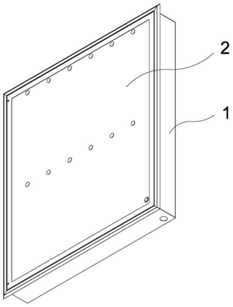 FIG. 1 — first structural schematic view of the medical imaging X-ray film viewer (illuminator)
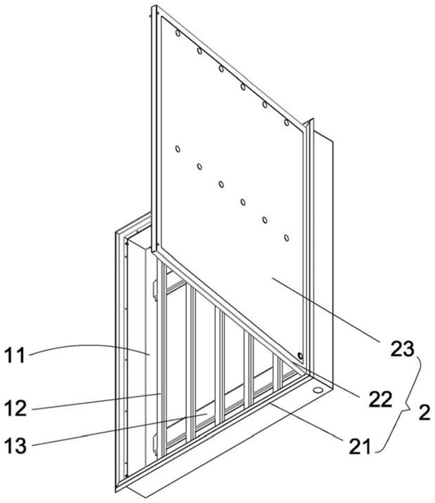 FIG. 2 — second structural schematic view of the medical imaging X-ray film viewer (illuminator)
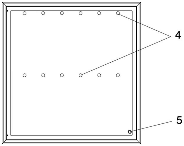 FIG. 3 — third structural schematic view of the medical imaging X-ray film viewer (illuminator)
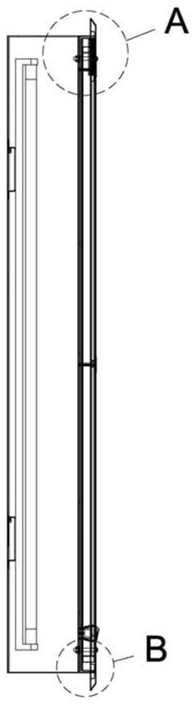 FIG. 4 — fourth structural schematic view of the medical imaging X-ray film viewer (illuminator)
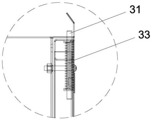 FIG. 5 — enlarged view of part A in FIG. 4
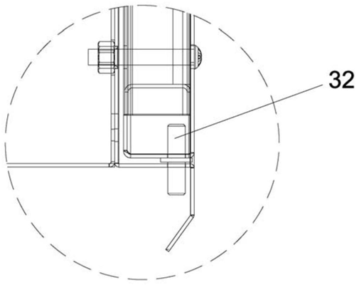 FIG. 6 — enlarged view of part B in FIG. 4
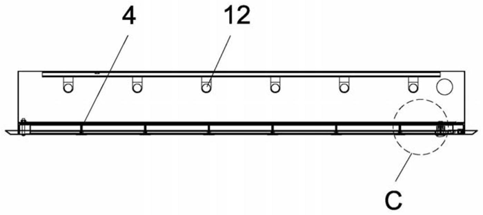 FIG. 7 — fifth structural schematic view of the medical imaging X-ray film viewer (illuminator)
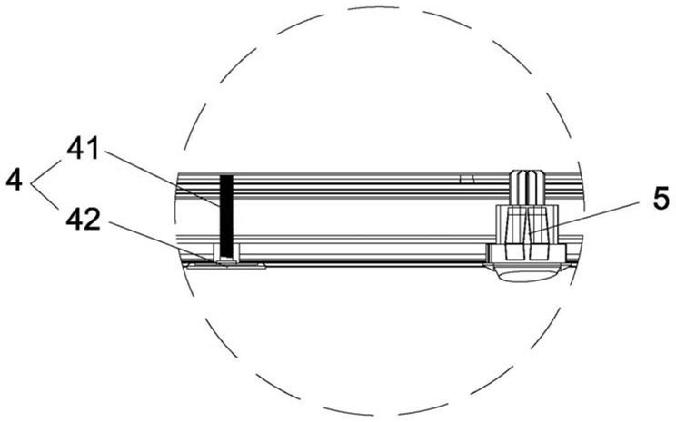 FIG. 8 — enlarged view of part C in FIG. 7