An Activated Carbon Filter (Utility Model CN 208382422 U)
The present utility model provides an activated carbon filter, comprising a housing, wherein the housing comprises an air inlet end and an air outlet end; an air outlet pipe is disposed at...
Abstract
The present utility model provides an activated carbon filter, comprising a housing, wherein the housing comprises an air inlet end and an air outlet end; an air outlet pipe is disposed at the air outlet end; a transparent glass plate is disposed at an upper end inside the housing; an upper side of the transparent glass plate forms a first mounting groove, and a lower side forms a second mounting groove; an ultraviolet sterilizing lamp is suspended in the first mounting groove; an activated carbon mesh layer, a cotton fiber layer, a photocatalyst filter layer, an oil absorption layer and a fan are sequentially disposed in the second mounting groove; a fragrance emitting device is further disposed at a lower side of the fan; and a dust scraping assembly is disposed on a side of the activated carbon mesh layer away from the cotton fiber layer. The activated carbon filter of the present utility model can perform air filtration efficiently, and is additionally provided with the ultraviolet sterilizing lamp and the fragrance emitting device, so that the filter has a sterilizing function and a function of improving air quality.
Patent Information
| Item | Detail |
|---|---|
| Issuing authority | National Intellectual Property Administration of the People’s Republic of China (CNIPA) |
| Document type | Utility Model Patent |
| Authorization publication number | CN 208382422 U |
| Authorization publication date | 15.01.2019 |
| Application number | 201821018235.3 |
| Filing date | 29.06.2018 |
| Patentee | Dongguan Pengchi Purification Technology Co., Ltd. |
| Address | Tangyilangwei Road, Tangjiao Village, Chashan Town, Dongguan City, Guangdong Province 523378, China |
| Inventors | Wang Haiou; Hu Guopeng; Li Dexiong |
| Patent agency | Dongguan Yongqiao Intellectual Property Agency (General Partnership) 44400 |
| Patent agent | He Xinhua |
| International Patent Classification (IPC) | F24F 3/16(2006.01); F24F 13/28(2006.01) |
| Title of utility model | An Activated Carbon Filter |
Claims
-
An activated carbon filter, characterized by comprising a housing (1), wherein the housing (1) comprises an air inlet end (11) and an air outlet end (12);
- an air outlet pipe (13) is disposed at the air outlet end (12);
- a transparent glass plate (14) is disposed at an upper end inside the housing (1);
- an upper side of the transparent glass plate (14) is a first mounting groove (15), and a lower side is a second mounting groove (16);
- an ultraviolet sterilizing lamp (2) is suspended in the first mounting groove (15);
- an activated carbon mesh layer (3), a cotton fiber layer (4), a photocatalyst filter layer (5), an oil absorption layer (6) and a fan (7) are sequentially disposed in the second mounting groove (16);
- a fragrance emitting device (8) is further disposed at a lower side of the fan (7);
- a dust scraping assembly (9) is disposed on a side of the activated carbon mesh layer (3) away from the cotton fiber layer (4).
-
The activated carbon filter according to claim 1, characterized in that the fragrance emitting device (8) comprises an aromatherapy box (81) located at a corner of the housing (1), a sachet (82) placed in the aromatherapy box (81), and an air pump (83) connected to one end of the aromatherapy box (81);
- an air outlet of the air pump (83) is disposed upward.
-
The activated carbon filter according to claim 2, characterized in that a pull door (17) is further disposed on the housing (1), and the pull door (17) is located on one side of the aromatherapy box (81).
-
The activated carbon filter according to claim 1, characterized in that the dust scraping assembly (9) comprises lead screws (91) located on two sides of the air inlet end (11), drive motors (92) connected to top ends of the lead screws (91), two sliders (93) in sliding connection with the lead screws (91), and a dust scraping plate (94) erected between the two sliders (93);
- the drive motors (92) are located in the first mounting groove (15);
- one end surface of the dust scraping plate (94) is parallel to a right side surface of the activated carbon mesh layer (3);
- a double-sided adhesive tape (941) is further attached to the dust scraping plate (94).
-
The activated carbon filter according to claim 1, characterized in that the cotton fiber layer (4) is honeycomb-shaped.
Description
TECHNICAL FIELD
[0001] The present utility model relates to the technical field of filters, and specifically relates to an activated carbon filter.
BACKGROUND ART
[0002] An activated carbon filter is a kind of filtering equipment used for purifying the air quality in public places, indoors, vehicle interiors and factory workshops. A common activated carbon filter has only one activated carbon filter layer, resulting in a relatively poor filtering effect; moreover, activated carbon is generally attached to a filter screen in an adhesion form and easily falls off, resulting in a relatively poor filtering effect.
SUMMARY OF THE UTILITY MODEL
[0003] In view of the above problems, the present utility model provides an activated carbon filter which can perform air filtration efficiently, and is additionally provided with an ultraviolet sterilizing lamp and a fragrance emitting device, so that the filter has a sterilizing function and a function of improving air quality.
[0004] To achieve the above objective, the present utility model solves the problems through the following technical solutions:
[0005] An activated carbon filter comprises a housing, wherein the housing comprises an air inlet end and an air outlet end; an air outlet pipe is disposed at the air outlet end; a transparent glass plate is disposed at an upper end inside the housing; an upper side of the transparent glass plate forms a first mounting groove, and a lower side forms a second mounting groove; an ultraviolet sterilizing lamp is suspended in the first mounting groove; an activated carbon mesh layer, a cotton fiber layer, a photocatalyst filter layer, an oil absorption layer and a fan are sequentially disposed in the second mounting groove; a fragrance emitting device is further disposed at a lower side of the fan; and a dust scraping assembly is disposed on a side of the activated carbon mesh layer away from the cotton fiber layer.
[0006] Specifically, the fragrance emitting device comprises an aromatherapy box located at a corner of the housing, a sachet placed in the aromatherapy box, and an air pump connected to one end of the aromatherapy box; and an air outlet of the air pump is disposed upward.
[0007] Specifically, a pull door is further disposed on the housing, and the pull door is located on one side of the aromatherapy box.
[0008] Specifically, the dust scraping assembly comprises lead screws located on two sides of the air inlet end, drive motors connected to top ends of the lead screws, two sliders in sliding connection with the lead screws, and a dust scraping plate erected between the two sliders; the drive motors are located in the first mounting groove; one end surface of the dust scraping plate is parallel to a right side surface of the activated carbon mesh layer; and a double-sided adhesive tape is further attached to the dust scraping plate.
[0009] Specifically, the cotton fiber layer is honeycomb-shaped.
[0010] The present utility model has the following beneficial effects:
[0011] First, in the activated carbon filter of the present utility model, an activated carbon mesh layer, a cotton fiber layer, a photocatalyst filter layer and an oil absorption layer are disposed on one side from the air inlet end to the air outlet end; air entering from the air inlet end is filtered in multiple layers, so that most of the dust and oil contamination can be removed; an ultraviolet sterilizing lamp is disposed at the upper end and can sterilize the air; an aromatherapy box is further disposed at the air outlet end, and a sachet is placed in the aromatherapy box; the fragrance of the sachet is emitted into the second mounting groove through the air pump and is discharged to the outside through the air outlet pipe, thereby playing a role in purifying the air;
[0012] Second, a dust scraping plate is disposed at a front end of the activated carbon mesh layer; the dust scraping plate can scrape off the dust accumulated at the front end of the activated carbon mesh layer through the up-and-down sliding of the sliders on the lead screws; and a double-sided adhesive tape is bonded to the dust scraping plate, and the double-sided adhesive tape can adhere to the dust and can be replaced at any time, thereby achieving an auxiliary dust removal effect.
BRIEF DESCRIPTION OF THE DRAWINGS
[0013] FIG. 1 is a structural schematic view of an activated carbon filter of the present utility model.
[0014] FIG. 2 is an enlarged view of part A in FIG. 1.
[0015] FIG. 3 is an enlarged view of part B in FIG. 1.
[0016] The reference numerals are as follows: housing 1, air inlet end 11, air outlet end 12, air outlet pipe 13, transparent glass plate 14, first mounting groove 15, second mounting groove 16, pull door 17, ultraviolet sterilizing lamp 2, activated carbon mesh layer 3, cotton fiber layer 4, photocatalyst filter layer 5, oil absorption layer 6, fan 7, fragrance emitting device 8, aromatherapy box 81, sachet 82, air pump 83, dust scraping assembly 9, lead screw 91, drive motor 92, slider 93, dust scraping plate 94, and double-sided adhesive tape 941.
DETAILED DESCRIPTION OF EMBODIMENTS
[0017] The present utility model is described in further detail below in combination with the embodiments and the accompanying drawings, but the embodiments of the present utility model are not limited thereto.
[0018] As shown in FIG. 1 to FIG. 3:
[0019] An activated carbon filter comprises a housing 1, wherein the housing 1 comprises an air inlet end 11 and an air outlet end 12; an air outlet pipe 13 is disposed at the air outlet end 12; a transparent glass plate 14 is disposed at an upper end inside the housing 1; an upper side of the transparent glass plate 14 forms a first mounting groove 15, and a lower side forms a second mounting groove 16; an ultraviolet sterilizing lamp 2 is suspended in the first mounting groove 15, and the ultraviolet sterilizing lamp 2 can sterilize air; an activated carbon mesh layer 3, a cotton fiber layer 4, a photocatalyst filter layer 5, an oil absorption layer 6 and a fan 7 are sequentially disposed in the second mounting groove 16; the oil absorption layer 6 can adsorb and remove oil contamination in the air; a fragrance emitting device 8 is further disposed at a lower side of the fan 7; and a dust scraping assembly 9 is disposed on a side of the activated carbon mesh layer 3 away from the cotton fiber layer 4.
[0020] Preferably, the fragrance emitting device 8 comprises an aromatherapy box 81 located at a corner of the housing 1, a sachet 82 placed in the aromatherapy box 81, and an air pump 83 connected to one end of the aromatherapy box 81; an air outlet of the air pump 83 is disposed upward; and the air pump 83 can pump the fragrance of the sachet 82 into the second mounting groove 16, and under the action of the fan 7, the fragrance is discharged to the outside from the air outlet pipe 13.
[0021] Preferably, a pull door 17 is further disposed on the housing 1, and the pull door 17 is located on one side of the aromatherapy box 81; after the pull door 17 is opened, the aromatherapy box 81 can be taken out, so that the sachet 82 can be placed or replaced.
[0022] Preferably, the dust scraping assembly 9 comprises lead screws 91 located on two sides of the air inlet end 11, drive motors 92 connected to top ends of the lead screws 91, two sliders 93 in sliding connection with the lead screws 91, and a dust scraping plate 94 erected between the two sliders 93; the drive motors 92 are located in the first mounting groove 15; one end surface of the dust scraping plate 94 is parallel to a right side surface of the activated carbon mesh layer 3; a double-sided adhesive tape 941 is further attached to the dust scraping plate 94; when the drive motors 92 are started, the lead screws 91 rotate, and the sliders 93 drive the dust scraping plate 94 to move downward; one end surface of the dust scraping plate 94 is in close contact with the right side surface of the activated carbon mesh layer 3, so that the dust on the right side surface of the activated carbon mesh layer 3 can be scraped off, and then the dust is adsorbed onto the double-sided adhesive tape 941, which avoids the situation where excessive dust accumulated on the surface of the activated carbon mesh layer 3 affects the dust removal work.
[0023] Preferably, the cotton fiber layer 4 is honeycomb-shaped, and the honeycomb-shaped cotton fiber layer 4 has better air permeability.
[0024] The above-mentioned embodiments only describe one embodiment of the present utility model, and the description thereof is relatively specific and detailed, but should not be construed as limiting the patent scope of the present utility model. It should be noted that, for a person of ordinary skill in the art, several variations and improvements can be made without departing from the concept of the present utility model, and all of these fall within the protection scope of the present utility model. Therefore, the protection scope of the present utility model patent shall be subject to the appended claims.
Drawings
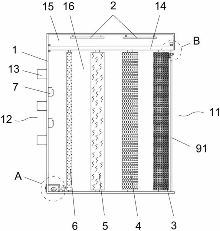 FIG. 1 — structural schematic view of the activated carbon filter
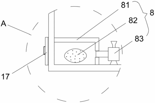 FIG. 2 — enlarged view of part A in FIG. 1
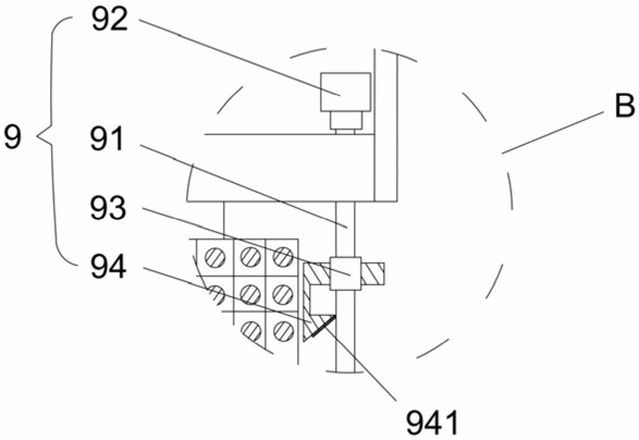 FIG. 3 — enlarged view of part B in FIG. 1