A Fresh-air System for Multi-level Underground Garages (Utility Model CN 208504649 U)
The present utility model provides a fresh-air system for multi-level underground garages, comprising an outer frame, wherein an air inlet chamber and an air outlet chamber are disposed in...
Abstract
The present utility model provides a fresh-air system for multi-level underground garages, comprising an outer frame, wherein an air inlet chamber and an air outlet chamber are disposed in the outer frame; an air intake system is disposed at an opening of the air inlet chamber; a plurality of air outlets in communication with the air inlet chamber are formed in parallel through one side of the outer frame; movable doors are hinged to the air outlets; the air inlet chamber comprises a transverse passage and a longitudinal passage in communication with each other; a slider in sliding connection with the longitudinal passage is disposed on the longitudinal passage; a flow passage is formed through the slider; a groove is formed in one side of the slider; an ejector rod is disposed in the groove; a spring is fixedly connected between the ejector rod and the groove; a motor is disposed at the bottom of the outer frame; the slider is in lead screw connection with the motor; and the slider moves up and down along the longitudinal passage under the driving of the motor; a plurality of air outlet mesh plates arranged in parallel are fixedly connected to one side of the outer frame; and a plurality of air outlet holes in communication with the air outlet chamber are formed through the air outlet mesh plates. A high-wind-speed air outlet effect can be achieved without using a high-power air intake system, which effectively saves energy.
Patent Information
| Item | Detail |
|---|---|
| Issuing authority | National Intellectual Property Administration of the People’s Republic of China (CNIPA) |
| Document type | Utility Model Patent |
| Authorization publication number | CN 208504649 U |
| Authorization publication date | 15.02.2019 |
| Application number | 201821018234.9 |
| Filing date | 29.06.2018 |
| Patentee | Dongguan Pengchi Purification Technology Co., Ltd. |
| Address | Tangyilangwei Road, Tangjiao Village, Chashan Town, Dongguan City, Guangdong Province 523378, China |
| Inventors | Wang Haiou; Hu Guopeng; Li Dexiong |
| Patent agency | Dongguan Yongqiao Intellectual Property Agency (General Partnership) 44400 |
| Patent agent | He Xinhua |
| International Patent Classification (IPC) | F24F 7/08(2006.01); F24F 13/28(2006.01) |
| Title of utility model | A Fresh-air System for Multi-level Underground Garages |
Claims
-
A fresh-air system for multi-level underground garages, comprising an outer frame (1), characterized in that an air inlet chamber (100) and an air outlet chamber (101) are disposed in parallel in the outer frame (1);
- an air intake system (2) is disposed at an opening of the air inlet chamber (100);
- a plurality of air outlets (102) in communication with the air inlet chamber (100) are formed in parallel through one side of the outer frame (1);
- a movable door (3) is hinged to each air outlet (102) through a torsion spring;
- the air inlet chamber (100) comprises a transverse passage (103) and a longitudinal passage (104) in communication with each other;
- a slider (4) matching the longitudinal passage (104) in shape is disposed on the longitudinal passage (104), and the slider (4) is in sliding connection with the longitudinal passage (104);
- a flow passage (40) is formed through the slider (4);
- the flow passage (40) comprises a flow passage inlet (400) disposed at the top of the slider (4) and a flow passage outlet (401) disposed on one side surface of the slider (4);
- a groove (41) is formed in one side of the slider (4);
- an ejector rod (5) is disposed in the groove (41);
- a spring (6) is fixedly connected between the ejector rod (5) and the groove (41);
- one end of the ejector rod (5) abuts against one side wall of the air inlet chamber (100) under the elastic force of the spring (6);
- a motor (7) is disposed at the bottom of the outer frame (1);
- the slider (4) is in lead screw connection with the motor (7), and the slider (4) moves up and down along the longitudinal passage (104) under the driving of the motor (7);
- a plurality of air outlet mesh plates (8) arranged in parallel are fixedly connected to one side of the outer frame (1);
- a plurality of air outlet holes (80) in communication with the air outlet chamber (101) are formed through the air outlet mesh plates (8).
-
The fresh-air system for multi-level underground garages according to claim 1, characterized in that the air intake system (2) comprises an outer cover (20) and a fan (9);
- an air delivery opening (200) in communication with the air inlet chamber (100) is formed through the outer cover (20);
- the fan (9) is fixedly connected to the air delivery opening (200);
- a filter (10) is fixedly connected to the air delivery opening (200) and located at an inner side of the fan (9).
-
The fresh-air system for multi-level underground garages according to claim 2, characterized in that a louver (11) is fixedly connected to the air delivery opening (200) and located at an outer side of the fan (9).
-
The fresh-air system for multi-level underground garages according to claim 1, characterized in that a round head (50) is disposed at one end of the ejector rod (5);
- a round groove portion (30) matching the round head (50) in shape is disposed on one side of the movable door (3).
-
The fresh-air system for multi-level underground garages according to claim 1, characterized in that an exhaust fan (12) is fixedly connected at an opening of the air outlet chamber (101).
Description
TECHNICAL FIELD
[0001] The present utility model relates to the technical field of air purification equipment, and specifically discloses a fresh-air system for multi-level underground garages.
BACKGROUND ART
[0002] An underground garage is a relatively enclosed space where air does not circulate and a large amount of automobile exhaust and dust exist, resulting in poor air quality. Long-term exposure to such an environment will seriously affect physical health and induce various respiratory diseases. Underground garages are generally provided with a plurality of floors, and in order to improve the air quality of the underground garages, fresh-air systems are often installed in the underground garages for air change.
[0003] Limited by the location conditions of the underground garages, the air intake system is generally disposed on a rooftop above the ground, and is in communication with the air intake system through a vertically-disposed delivery frame body which then distributes the air to air outlets of the garages on all floors. Since the floors are high, and at the same time the air supply distributed to the garages on all floors requires a great delivery power to meet a specific wind speed requirement, such a fresh-air system has high energy consumption and is in great need of improvement.
SUMMARY OF THE UTILITY MODEL
[0004] Based on this, it is necessary to provide, in view of the problems in the prior art, a fresh-air system for multi-level underground garages which has a unique structure, can achieve a high-wind-speed air outlet effect without using a high-power air intake system, and effectively saves energy.
[0005] To solve the problems in the prior art, the present utility model discloses a fresh-air system for multi-level underground garages, comprising an outer frame, wherein an air inlet chamber and an air outlet chamber are disposed in parallel in the outer frame; an air intake system is disposed at an opening of the air inlet chamber; a plurality of air outlets in communication with the air inlet chamber are formed in parallel through one side of the outer frame; movable doors are hinged to the air outlets through torsion springs; the air inlet chamber comprises a transverse passage and a longitudinal passage in communication with each other; a slider matching the longitudinal passage in shape is disposed on the longitudinal passage; the slider is in sliding connection with the longitudinal passage; a flow passage is formed through the slider; the flow passage comprises a flow passage inlet disposed at the top of the slider and a flow passage outlet disposed on one side surface of the slider; a groove is formed in one side of the slider; an ejector rod is disposed in the groove; a spring is fixedly connected between the ejector rod and the groove; one end of the ejector rod abuts against one side wall of the air inlet chamber under the elastic force of the spring; a motor is disposed at the bottom of the outer frame; the slider is in lead screw connection with the motor; the slider moves up and down along the longitudinal passage under the driving of the motor; a plurality of air outlet mesh plates arranged in parallel are fixedly connected to one side of the outer frame; and a plurality of air outlet holes in communication with the air outlet chamber are formed through the air outlet mesh plates.
[0006] Preferably, the air intake system comprises an outer cover and a fan; an air delivery opening in communication with the air inlet chamber is formed through the outer cover; the fan is fixedly connected to the air delivery opening; and a filter is fixedly connected to the air delivery opening and located at an inner side of the fan.
[0007] Preferably, a louver is fixedly connected to the air delivery opening and located at an outer side of the fan.
[0008] Preferably, a round head is disposed at one end of the ejector rod, and a round groove portion matching the round head in shape is disposed on one side of the movable door.
[0009] Preferably, an exhaust fan is fixedly connected at an opening of the air outlet chamber.
[0010] The present utility model has the following beneficial effects: the present utility model discloses a fresh-air system for multi-level underground garages with a unique structure; the outer frame is disposed on a wall body of the underground garage, the air intake system is in communication with the outdoors, and the air outlets are in communication with garages on different floors respectively. When the air intake system works, outdoor air is delivered into the air inlet chamber, and the motor drives the slider to move up and down along the longitudinal passage. When the slider moves to a front side of a movable door, the ejector rod pushes the movable door open under the elastic force of the spring, and the air in the air inlet chamber flows from the air outlet through the flow passage into a certain garage floor. Since only one movable door is opened at the same time, the air delivered from the air outlet can be ensured to have a relatively high wind speed; and by cyclically driving the slider to move up and down along the longitudinal passage, air can be cyclically supplied to the garages on all floors. The system is simple in structure, can achieve a high-wind-speed air outlet effect without using a high-power air intake system, and effectively saves energy.
BRIEF DESCRIPTION OF THE DRAWINGS
[0011] FIG. 1 is a cross-sectional structural schematic view of the fresh-air system of the present utility model.
[0012] FIG. 2 is an external structural schematic view of the fresh-air system of the present utility model.
[0013] FIG. 3 is a front-view structural schematic view of the outer frame of the present utility model.
[0014] The reference numerals are as follows: outer frame 1, air inlet chamber 100, air outlet chamber 101, air outlet 102, transverse passage 103, longitudinal passage 104, air intake system 2, outer cover 20, air delivery opening 200, movable door 3, round groove portion 30, slider 4, flow passage 40, flow passage inlet 400, flow passage outlet 401, groove 41, ejector rod 5, round head 50, spring 6, motor 7, air outlet mesh plate 8, air outlet hole 80, fan 9, filter 10, louver 11, and exhaust fan 12.
DETAILED DESCRIPTION OF EMBODIMENTS
[0015] To further understand the features, technical means, and specific objectives and functions achieved by the present utility model, the present utility model is described in further detail below with reference to the accompanying drawings and specific embodiments.
[0016] Reference is made to FIG. 1 to FIG. 3.
[0017] An embodiment of the present utility model discloses a fresh-air system for multi-level underground garages, comprising an outer frame 1, wherein an air inlet chamber 100 and an air outlet chamber 101 are disposed in parallel in the outer frame 1; an air intake system 2 is disposed at an opening of the air inlet chamber 100; a plurality of air outlets 102 in communication with the air inlet chamber 100 are formed in parallel through one side of the outer frame 1; a movable door 3 is hinged to each air outlet 102 through a torsion spring; the air inlet chamber 100 comprises a transverse passage 103 and a longitudinal passage 104 in communication with each other; a slider 4 matching the longitudinal passage 104 in shape is disposed on the longitudinal passage 104; the slider 4 is in sliding connection with the longitudinal passage 104; a flow passage 40 is formed through the slider 4; the flow passage 40 comprises a flow passage inlet 400 disposed at the top of the slider 4 and a flow passage outlet 401 disposed on one side surface of the slider 4; a groove 41 is formed in one side of the slider 4; an ejector rod 5 is disposed in the groove 41; a spring 6 is fixedly connected between the ejector rod 5 and the groove 41; one end of the ejector rod 5 abuts against one side wall of the air inlet chamber 100 under the elastic force of the spring 6; a motor 7 is disposed at the bottom of the outer frame 1; the slider 4 is in lead screw connection with the motor 7; the slider 4 moves up and down along the longitudinal passage 104 under the driving of the motor 7; a plurality of air outlet mesh plates 8 arranged in parallel are fixedly connected to one side of the outer frame 1; and a plurality of air outlet holes 80 in communication with the air outlet chamber 101 are formed through the air outlet mesh plates 8.
[0018] In specific use, the outer frame 1 is disposed on a wall body of the underground garage, the air intake system 2 is in communication with the outdoors, and the air outlets 102 are in communication with garages on different floors respectively. When the air intake system 2 works, outdoor air is delivered into the air inlet chamber 100, and the motor 7 drives the slider 4 to move up and down along the longitudinal passage 104. When the slider 4 moves to the front side of a movable door 3, the ejector rod 5 pushes the movable door 3 open under the elastic force of the spring 6, and the air in the air inlet chamber 100 flows from the air outlet 102 through the flow passage 40 into a certain garage floor. Since only one movable door 3 is pushed open at the same time, the air delivered from the air outlet 102 can be ensured to have a relatively high wind speed; and by cyclically driving the slider 4 to move up and down along the longitudinal passage 104, air can be cyclically supplied to the garages on all floors. The system is simple in structure, can achieve a high-wind-speed air outlet effect without using a high-power air intake system, and effectively saves energy.
[0019] Based on the above embodiment, the air intake system 2 comprises an outer cover 20 and a fan 9; an air delivery opening 200 in communication with the air inlet chamber 100 is formed through the outer cover 20; the fan 9 is fixedly connected to the air delivery opening 200; and a filter 10 is fixedly connected to the air delivery opening 200 and located at an inner side of the fan 9. Outdoor air is drawn into the air inlet chamber 100 through the fan 9, and the filter 10 can filter the drawn air so as to improve the air quality.
[0020] Based on the above embodiment, a louver 11 is fixedly connected to the air delivery opening 200 and located at an outer side of the fan 9. The louver 11 is disposed at the outer side of the fan 9, which effectively blocks large foreign matters from entering the air delivery opening 200; and when air supply is not performed, the louver 11 can be closed to prevent dust and rainwater from entering the air inlet chamber 100 through the air delivery opening 200.
[0021] Based on the above embodiment, a round head 50 is disposed at one end of the ejector rod 5, and a round groove portion 30 matching the round head 50 in shape is disposed on one side of the movable door 3. When the ejector rod 5 abuts against the movable door 3, the round head 50 is embedded in the round groove portion 30, which improves the stability of the ejector rod 5 in jacking up the movable door 3.
[0022] Based on the above embodiment, an exhaust fan 12 is fixedly connected at an opening of the air outlet chamber 101. By starting the exhaust fan 12, the discharge speed of exhaust gas in the garage can be enhanced, and the air change effect of the garage is improved.
[0023] The above embodiments only describe one embodiment of the present utility model, and the description thereof is relatively specific and detailed, but should not be construed as limiting the patent scope of the present utility model. It should be noted that, for a person of ordinary skill in the art, several variations and improvements can be made without departing from the concept of the present utility model, and all of these fall within the protection scope of the present utility model. Therefore, the protection scope of the present utility model patent shall be subject to the appended claims.
Drawings
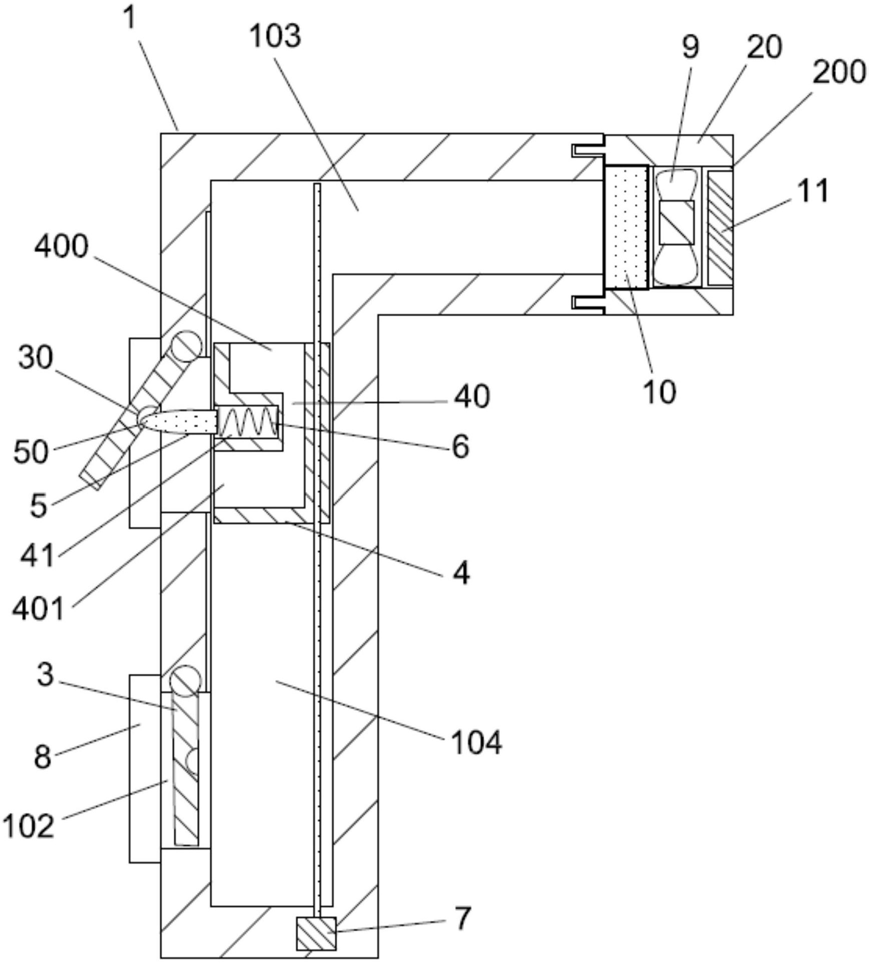 FIG. 1 — cross-sectional structural schematic view of the fresh-air system
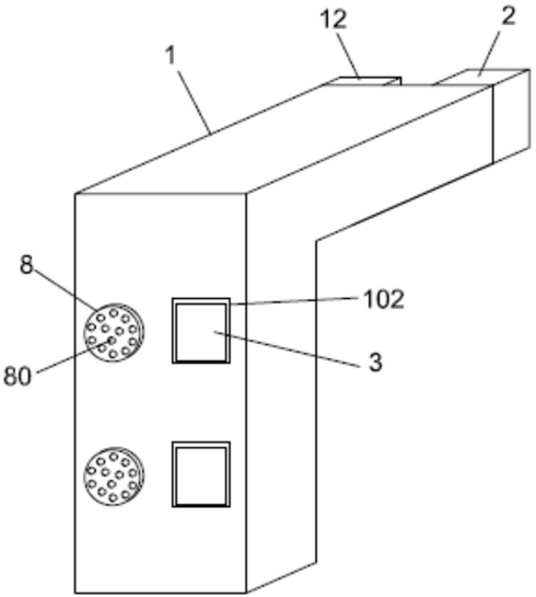 FIG. 2 — external structural schematic view of the fresh-air system
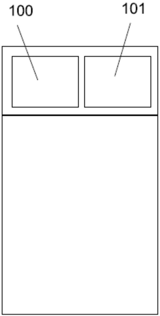 FIG. 3 — front-view structural schematic view of the outer frame