An Improved Smoke-and-Dust Air Treatment Unit (Utility Model CN 208493568 U)
The present utility model relates to the technical field of air purification treatment, and in particular to an improved smoke-and-dust air treatment unit. The box body is partitioned into...
Abstract
The present utility model relates to the technical field of air purification treatment, and in particular to an improved smoke-and-dust air treatment unit. The box body is partitioned into a first filtering space, a second filtering space, and a third filtering space; the first filtering space filters some dust of relatively large volume. Under the condition that an induced draft fan promotes air flow, the air, after the relatively large dust has been filtered out, passes through multiple filter plate layers and enters the second filtering space; the second filtering space mainly filters bacteria in the air by irradiation of sunlight; the air after completion of filtration enters the third filtering space for ultraviolet filtration, and the filtered air is then discharged from an air outlet under the action of an exhaust fan. Through the three-layer filtration structure, a good smoke-and-dust air filtration effect is thereby achieved.
Patent Information
| Item | Detail |
|---|---|
| Issuing authority | National Intellectual Property Administration of the People’s Republic of China (CNIPA) |
| Document type | Utility Model Patent |
| Authorization publication number | CN 208493568 U |
| Authorization publication date | 2019.02.15 |
| Application number | 201821017789.1 |
| Filing date | 2018.06.29 |
| Patentee | Dongguan Pengchi Purification Technology Co., Ltd. |
| Address | Tangyilangwei Road, Tangjiao Village, Chashan Town, Dongguan City, Guangdong Province 523378, China |
| Inventors | Wang Haiou; Hu Guopeng; Li Dexiong |
| Patent agency | Dongguan Yongqiao Intellectual Property Agency (General Partnership), Code 44400 |
| Patent agent | He Xinhua |
| International Patent Classification (IPC) | B01D 46/00 (2006.01); B01D 50/00 (2006.01); B01L 9/00 (2006.01) |
| Title of utility model | An Improved Smoke-and-Dust Air Treatment Unit |
Claims
-
An improved smoke-and-dust air treatment unit, comprising a box body, characterized in that a first filtering space (10), a second filtering space (18), and a third filtering space (15) are separately provided in the box body, the first filtering space (10) communicates with the second filtering space (18), and the second filtering space (18) communicates with the third filtering space (15);
- an air inlet (22) is defined at the top of the first filtering space (10), and an induced draft fan (21) communicating with the air inlet (22) is provided in an inner cavity of the first filtering space (10); an activated carbon filter plate layer (23) is fixedly provided on a side of the air inlet (22) facing the inner cavity of the first filtering space (10); a water tank (13) is provided at a lower portion of the inner cavity of the first filtering space (10) at a position corresponding to the air inlet (22);
- a plurality of filter plate layers (20) are arranged in an array at the position where the first filtering space (10) communicates with the second filtering space (18); a plurality of light-transmitting windows (19) are defined in the second filtering space (18), and a transparent glass layer is hermetically fixed at each light-transmitting window (19); a photocatalytic material layer is coated on an inner cavity wall of the second filtering space (18);
- a plurality of ultraviolet light bars (14) are fixedly provided in an inner cavity of the third filtering space (15) at a position adjacent to the communication with the second filtering space (18); an air outlet (16) is defined at one side of the third filtering space (15); and an exhaust fan (17) is provided in communication at the air outlet (16) on a side facing the inner cavity of the third filtering space (15).
-
The improved smoke-and-dust air treatment unit according to claim 1, characterized in that one side of the water tank (13) extends, via a water inlet pipe (11), through to the outside of the box body and communicates with a water supply device (32), and the other side of the water tank (13) extends, via a water outlet pipe (12), through to the outside of the box body and communicates with a sewage reservoir (33); a water pump (34) is connected between the water outlet pipe (12) and the sewage reservoir (33).
-
The improved smoke-and-dust air treatment unit according to claim 1, characterized in that a fan mechanism (30) is fixedly provided on an inner cavity wall of the first filtering space (10) at a position adjacent to the air inlet (22), the fan mechanism (30) comprising a motor (31) fixed on an outer wall of the box body, a rotating shaft (29) connected to a power output end of the motor (31) and extending into the first filtering space (10), and fan blades (28) provided in the first filtering space (10) and connected to a free end of the rotating shaft (29).
-
The improved smoke-and-dust air treatment unit according to claim 1, characterized in that the number of filter plate layers (20) is three, and the filter plate layers (20) are, in sequence, an anti-mite filter plate layer, a deodorizing filter plate layer, and a formaldehyde-removing filter plate layer.
-
The improved smoke-and-dust air treatment unit according to claim 1, characterized in that a fragrance mechanism (27) is fixedly provided in the third filtering space (15) on an inner cavity wall adjacent to the air outlet, the fragrance mechanism (27) comprising a fan (24) fixed to the inner cavity wall of the third filtering space (15) and a fragrance box (25) communicating with an air outlet of the fan, and a plurality of ventilation holes (26) being defined in the fragrance box (25) at positions corresponding to the air outlet of the fan.
-
The improved smoke-and-dust air treatment unit according to claim 1, characterized in that the number of ultraviolet light bars (14) is one or more.
Description
TECHNICAL FIELD
[0001] The present utility model relates to the technical field of air purification treatment, and in particular to an improved smoke-and-dust air treatment unit.
BACKGROUND ART
[0002] Smoke-and-dust pollution refers to the degradation of air quality caused by particulate pollutants in the air. The impacts and hazards caused by smoke-and-dust pollution are multifaceted; particles with a diameter below 5 μm in the atmosphere can enter the human bronchi and even the deep portions of the lungs. It is reported that when the concentration of such fine particles in the atmosphere is 100 μg/m³, respiratory tract infections in children increase significantly, and when the concentration is 200 μg/m³, the mortality rate of children from chronic respiratory diseases increases. To reduce the hazards caused by smoke-and-dust pollution to the human body, air treatment units are installed in many places. The air treatment units in the prior art generally have only a single filtering device for filtering smoke-and-dust air, and the filtering effect needs to be improved.
SUMMARY OF THE UTILITY MODEL
[0003] In view of this, an object of the present utility model is to provide an improved smoke-and-dust air treatment unit having a multi-layer filtration structure, so that the product achieves a good smoke-and-dust air filtration effect.
[0004] The present utility model provides an improved smoke-and-dust air treatment unit, comprising a box body, a first filtering space, a second filtering space, and a third filtering space being separately provided in the box body, the first filtering space communicating with the second filtering space, and the second filtering space communicating with the third filtering space.
[0005] An air inlet is defined at the top of the first filtering space, and an induced draft fan communicating with the air inlet is provided in an inner cavity of the first filtering space; an activated carbon filter plate layer is fixedly provided on a side of the air inlet facing the inner cavity of the first filtering space; a water tank is provided at a lower portion of the inner cavity of the first filtering space at a position corresponding to the air inlet.
[0006] A plurality of filter plate layers are arranged in an array at the position where the first filtering space communicates with the second filtering space; a plurality of light-transmitting windows are defined in the second filtering space, and a transparent glass layer is hermetically fixed at each light-transmitting window; a photocatalytic material layer is coated on an inner cavity wall of the second filtering space.
[0007] A plurality of ultraviolet light bars are fixedly provided in an inner cavity of the third filtering space at a position adjacent to the communication with the second filtering space; an air outlet is defined at one side of the third filtering space; and an exhaust fan is provided in communication at the air outlet on a side facing the inner cavity of the third filtering space.
[0008] As a preferred solution, one side of the water tank extends, via a water inlet pipe, through to the outside of the box body and communicates with a water supply device, and the other side of the water tank extends, via a water outlet pipe, through to the outside of the box body and communicates with a sewage reservoir; a water pump is connected between the water outlet pipe and the sewage reservoir.
[0009] As a preferred solution, a fan mechanism is fixedly provided on an inner cavity wall of the first filtering space at a position adjacent to the air inlet, the fan mechanism comprising a motor fixed on an outer wall of the box body, a rotating shaft connected to a power output end of the motor and extending into the first filtering space, and fan blades provided in the first filtering space and connected to a free end of the rotating shaft.
[0010] As a preferred solution, the number of filter plate layers is three, and the filter plate layers are, in sequence, an anti-mite filter plate layer, a deodorizing filter plate layer, and a formaldehyde-removing filter plate layer.
[0011] As a preferred solution, a fragrance mechanism is fixedly provided in the third filtering space on an inner cavity wall adjacent to the air outlet, the fragrance mechanism comprising a fan fixed to the inner cavity wall of the third filtering space and a fragrance box communicating with an air outlet of the fan, and a plurality of ventilation holes being defined in the fragrance box at positions corresponding to the air outlet of the fan.
[0012] As a preferred solution, the number of ultraviolet light bars is one or more.
[0013] The present utility model has the following beneficial effects:
[0014] 1. The box body is partitioned into a first filtering space, a second filtering space, and a third filtering space; the first filtering space filters some dust of relatively large volume; under the condition that the induced draft fan promotes air flow, the air, after the relatively large dust has been filtered out, passes through the multiple filter plate layers and enters the second filtering space; the second filtering space mainly filters bacteria in the air by irradiation of sunlight; the air after completion of filtration enters the third filtering space for ultraviolet filtration, and the filtered air is then discharged from the air outlet under the action of the exhaust fan; through the three-layer filtration structure, a good smoke-and-dust air filtration effect is thereby achieved;
[0015] 2. A water tank is provided, and relatively large dust filtered through the first filtering space falls into the water tank, avoiding re-entrainment which would affect the filtration effect of the next stage;
[0016] 3. A fan mechanism is provided, by which the air flow velocity in the first filtering space is increased, improving the efficiency of air filtration;
[0017] 4. A fragrance mechanism is provided, so that the product can emit fragrant air according to the needs of the use environment.
BRIEF DESCRIPTION OF THE DRAWINGS
[0018] FIG. 1 is a schematic structural view of the present utility model.
[0019] FIG. 2 is a schematic structural view of another embodiment of the present utility model (showing the fragrance mechanism, the fan mechanism, the sewage reservoir, and the water supply device).
[0020] The reference numerals are as follows: first filtering space 10; water inlet pipe 11; water outlet pipe 12; water tank 13; ultraviolet light bar 14; third filtering space 15; air outlet 16; exhaust fan 17; second filtering space 18; light-transmitting window 19; filter plate layer 20; air inlet 22; induced draft fan 21; activated carbon filter plate layer 23; fan 24; fragrance box 25; ventilation hole 26; fragrance mechanism 27; fan blades 28; rotating shaft 29; fan mechanism 30; motor 31; water supply device 32; sewage reservoir 33; water pump 34.
DETAILED DESCRIPTION OF EMBODIMENTS
[0021] To enable a further understanding of the features, technical means, and the specific objectives and functions achieved by the present utility model, the present utility model is described in further detail below in conjunction with the accompanying drawings and the detailed description of embodiments.
[0022] Referring to FIG. 1, an improved smoke-and-dust air treatment unit comprises a box body, a first filtering space 10, a second filtering space 18, and a third filtering space 15 being separately provided in the box body, the first filtering space 10 communicating with the second filtering space 18, and the second filtering space 18 communicating with the third filtering space 15.
[0023] An air inlet 22 is defined at the top of the first filtering space 10, and an induced draft fan 21 communicating with the air inlet 22 is provided in an inner cavity of the first filtering space 10; an activated carbon filter plate layer 23 is fixedly provided on a side of the air inlet 22 facing the inner cavity of the first filtering space 10; a water tank 13 is provided at a lower portion of the inner cavity of the first filtering space 10 at a position corresponding to the air inlet 22.
[0024] A plurality of filter plate layers 20 are arranged in an array at the position where the first filtering space 10 communicates with the second filtering space 18; a plurality of light-transmitting windows 19 are defined in the second filtering space 18, and a transparent glass layer is hermetically fixed at each light-transmitting window 19; a photocatalytic material layer is coated on an inner cavity wall of the second filtering space 18.
[0025] A plurality of ultraviolet light bars 14 are fixedly provided in an inner cavity of the third filtering space 15 at a position adjacent to the communication with the second filtering space 18; an air outlet 16 is defined at one side of the third filtering space 15; and an exhaust fan 17 is provided in communication at the air outlet 16 on a side facing the inner cavity of the third filtering space 15.
[0026] The operating principle of the present utility model is as follows: after the power switch is turned on, the induced draft fan 21 and the exhaust fan 17 are started respectively; under the action of the induced draft fan 21, smoke-and-dust air passes from the air inlet 22 through the activated carbon filter plate layer 23 and enters the first filtering space 10; a portion of the dust of relatively large volume falls into the water tank 13; the induced draft fan 21 causes the air to flow in the first filtering space 10, and the air penetrates the multiple filter plate layers 20 and enters the second filtering space 18; in the second filtering space 18, the air is sterilized by irradiation of sunlight in combination with the action of the photocatalytic material layer; the air then enters the third filtering space 15, where it is sterilized by the ultraviolet light bars 14, after which, under the action of the induced draft fan 21, the air that has completed the three-layer filtration is discharged through the air outlet 16.
[0027] As a preferred embodiment, the number of filter plate layers 20 is three, and the filter plate layers 20 are, in sequence, an anti-mite filter plate layer, a deodorizing filter plate layer, and a formaldehyde-removing filter plate layer.
[0028] As a preferred embodiment, the number of ultraviolet light bars 14 is one or more.
[0029] Referring to FIG. 2, as a preferred embodiment, one side of the water tank 13 extends, via a water inlet pipe 11, through to the outside of the box body and communicates with a water supply device 32, and the other side of the water tank 13 extends, via a water outlet pipe 12, through to the outside of the box body and communicates with a sewage reservoir 33; a water pump 34 is connected between the water outlet pipe 12 and the sewage reservoir 33. The water supply device 32 supplies clean water to the water tank 13, and the water in the water tank 13 is replaced periodically; the water pump 34 discharges the waste water along the water outlet pipe 12 into the sewage reservoir 33, and the water supply device 32 then delivers clean water through the water inlet pipe 11 into the water tank 13 for continued use. Through the provision of the water tank 13, re-entrainment of dust, which would affect the filtration effect of the next stage, is avoided.
[0030] Referring to FIG. 2, as a preferred embodiment, a fan mechanism 30 is fixedly provided on an inner cavity wall of the first filtering space 10 at a position adjacent to the air inlet 22, the fan mechanism 30 comprising a motor 31 fixed on an outer wall of the box body, a rotating shaft 29 connected to a power output end of the motor 31 and extending into the first filtering space 10, and fan blades 28 provided in the first filtering space 10 and connected to a free end of the rotating shaft 29. When the motor 31 is started, the power output of the motor 31 drives the fan blades 28 to rotate via the rotating shaft 29, thereby increasing the air flow velocity in the first filtering space 10 by means of the fan blades 28.
[0031] Referring to FIG. 2, as a preferred embodiment, a fragrance mechanism 27 is fixedly provided in the third filtering space 15 on an inner cavity wall adjacent to the air outlet, the fragrance mechanism 27 comprising a fan 24 fixed to the inner cavity wall of the third filtering space 15 and a fragrance box 25 communicating with an air outlet of the fan, and a plurality of ventilation holes 26 being defined in the fragrance box 25 at positions corresponding to the air outlet of the fan. When the fan 24 is started, the air from the fan 24 blows toward the fragrance box 25, and the fragrance in the fragrance box 25 is emitted through the ventilation holes 26 into the third filtering space 15 and then, under the action of the induced draft fan 21, discharged out of the box body, so that the product can emit fragrant air according to the needs of the use environment.
[0032] The above-described embodiments merely express several implementations of the present utility model, and the descriptions thereof are relatively specific and detailed, but they should not be construed as limiting the patent scope of the present utility model. It should be noted that, for a person of ordinary skill in the art, various modifications and improvements may further be made without departing from the concept of the present utility model, and such modifications and improvements all fall within the protection scope of the present utility model. Therefore, the protection scope of the present utility model patent shall be subject to the appended claims.
Drawings
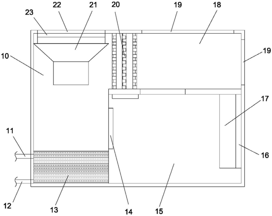 FIG. 1 — Schematic structural view of the improved smoke-and-dust air treatment unit
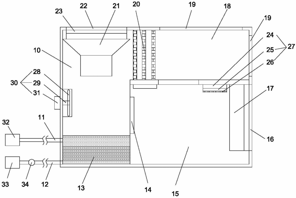 FIG. 2 — Schematic structural view of another embodiment, showing the fragrance mechanism, the fan mechanism, the sewage reservoir, and the water supply device