A Tunnel Ventilation Device (Utility Model CN 208380620 U)
The present utility model relates to the technical field of tunnel ventilation treatment, and in particular to a tunnel ventilation device, comprising a main ventilation duct arranged at...
Abstract
The present utility model relates to the technical field of tunnel ventilation treatment, and in particular to a tunnel ventilation device, comprising a main ventilation duct arranged at the top of an inner cavity of a tunnel, the main ventilation duct being arranged along the length direction of the tunnel. One end of the main ventilation duct extends out of the tunnel to form an air inlet, and an induced draft fan is provided at the air inlet. An air filtering device communicating with the air inlet is provided on the main ventilation duct at a position adjacent to the air inlet, and a plurality of air outlets A are defined at the bottom of the main ventilation duct along the length direction of the tunnel. Since the air filtering device communicating with the air inlet is provided on the main ventilation duct at a position adjacent to the air inlet, the air entering the main ventilation duct from the air inlet is filtered in an air filter chamber and then dried in an air drying chamber, after which it enters the inner cavity of the tunnel through the air outlets A; the filtered clean air enters the inner cavity of the tunnel, thereby achieving the purpose of effectively reducing pollutant discharge.
Patent Information
| Item | Detail |
|---|---|
| Issuing authority | National Intellectual Property Administration of the People’s Republic of China (CNIPA) |
| Document type | Utility Model Patent |
| Authorization publication number | CN 208380620 U |
| Authorization publication date | 2019.01.15 |
| Application number | 201821017788.7 |
| Filing date | 2018.06.29 |
| Patentee | Dongguan Pengchi Purification Technology Co., Ltd. |
| Address | Tangyilangwei Road, Tangjiao Village, Chashan Town, Dongguan City, Guangdong Province 523378, China |
| Inventors | Wang Haiou; Hu Guopeng; Li Dexiong |
| Patent agency | Dongguan Yongqiao Intellectual Property Agency (General Partnership), Code 44400 |
| Patent agent | He Xinhua |
| International Patent Classification (IPC) | E21F 1/00 (2006.01); E21F 5/20 (2006.01) |
| Title of utility model | A Tunnel Ventilation Device |
Claims
-
A tunnel ventilation device, comprising:
- a main ventilation duct (13) arranged at the top of an inner cavity of a tunnel (10), the main ventilation duct (13) being arranged along a length direction of the tunnel (10), one end of the main ventilation duct (13) extending out of the tunnel to form an air inlet (12), an induced draft fan (18) being provided at the air inlet (12), an air filtering device communicating with the air inlet (12) being provided on the main ventilation duct (13) at a position adjacent to the air inlet (12), and a plurality of air outlets A (25) being defined at the bottom of the main ventilation duct (13) along the length direction of the tunnel;
- wherein the air filtering device comprises an air filter chamber (27) communicating with the air inlet (12), a dust collection chamber (22) arranged below the air filter chamber (27), and an air drying chamber (24) communicating with the air filter chamber (27); a filter screen A (21), a filter screen B (20), and a filter screen C (19) are fixedly arranged in the air filter chamber (27) in sequence from the direction of the air inlet (12) toward the direction of the air drying chamber (24); the air filter chamber (27) communicates with the dust collection chamber (22), and a dust discharge port (23) is provided at the bottom of the dust collection chamber (22); a blower (11) is provided at the position where the air filter chamber (27) communicates with the air drying chamber (24); an air dryer (16) is provided in the air drying chamber (24); and the air drying chamber (24) communicates with the main ventilation duct (13).
-
The tunnel ventilation device according to claim 1, characterized in that an air humidity sensor (17) is provided on the main ventilation duct (13) at a position adjacent to each air outlet A (25).
-
The tunnel ventilation device according to claim 1, characterized in that a plurality of branch ventilation ducts (15) are provided on both sides of the main ventilation duct (13) along a width direction of the tunnel, and each branch ventilation duct (15) is provided with a plurality of air outlets B (14) communicating with the inner cavity of the tunnel.
-
The tunnel ventilation device according to claim 3, characterized in that an induced draft fan (18) is provided at a tail end of each branch ventilation duct (15).
-
The tunnel ventilation device according to claim 1, characterized in that a filter screen layer D (28) is fixed at each air outlet A (25).
-
The tunnel ventilation device according to claim 1, characterized in that the main ventilation duct (13) is fixed to the inner cavity of the tunnel via a support bracket.
Description
TECHNICAL FIELD
[0001] The present utility model relates to the technical field of tunnel ventilation treatment, and in particular to a tunnel ventilation device.
BACKGROUND ART
[0002] With the continuous advancement of urbanization, the construction of road tunnels plays an important role in alleviating traffic congestion on main roads in central urban areas and in reducing environmental pollution on road surfaces. Since tunnels are all closed structures, the pollutants produced by vehicle traffic mainly include dust, carbon monoxide, hydrocarbons, and nitrogen oxides. To ensure the air quality in a tunnel, a suitable ventilation system needs to be configured during tunnel design so as to control the concentrations of various pollutants therein. The tunnel ventilation equipment in the prior art can mainly achieve ventilation, but very few have an air purification function, with the result that the purpose of effectively reducing pollutant discharge is not achieved. In view of the defects existing in the prior art, an urgent solution is required.
SUMMARY OF THE UTILITY MODEL
[0003] In view of this, an object of the present utility model is to provide a tunnel ventilation device in which, by adjusting the structure of the ventilation device, an air purification function is additionally provided on the basis of ensuring ventilation.
[0004] The present utility model provides a tunnel ventilation device, comprising a main ventilation duct arranged at the top of an inner cavity of a tunnel, the main ventilation duct being arranged along the length direction of the tunnel; one end of the main ventilation duct extends out of the tunnel to form an air inlet, and an induced draft fan is provided at the air inlet; an air filtering device communicating with the air inlet is provided on the main ventilation duct at a position adjacent to the air inlet, and a plurality of air outlets A are defined at the bottom of the main ventilation duct along the length direction of the tunnel.
[0005] The air filtering device comprises an air filter chamber communicating with the air inlet, a dust collection chamber arranged below the air filter chamber, and an air drying chamber communicating with the air filter chamber; a filter screen A, a filter screen B, and a filter screen C are fixedly arranged in the air filter chamber in sequence from the direction of the air inlet toward the direction of the air drying chamber; the air filter chamber communicates with the dust collection chamber, and a dust discharge port is provided at the bottom of the dust collection chamber; a blower is provided at the position where the air filter chamber communicates with the air drying chamber; an air dryer is provided in the air drying chamber; and the air drying chamber communicates with the main ventilation duct.
[0006] As a preferred solution, an air humidity sensor is provided on the main ventilation duct at a position adjacent to each air outlet A.
[0007] As a preferred solution, a plurality of branch ventilation ducts are provided on both sides of the main ventilation duct along the width direction of the tunnel, and each branch ventilation duct is provided with a plurality of air outlets B communicating with the inner cavity of the tunnel.
[0008] As a preferred solution, an induced draft fan is provided at a tail end of each branch ventilation duct.
[0009] As a preferred solution, a filter screen layer D is fixed at each air outlet A.
[0010] As a preferred solution, the main ventilation duct is fixed to the inner cavity of the tunnel via a support bracket.
[0011] The present utility model has the following beneficial effects:
[0012] 1. The air filtering device communicating with the air inlet is provided on the main ventilation duct at a position adjacent to the air inlet, so that the air entering the main ventilation duct from the air inlet is filtered in the air filter chamber and then dried in the air drying chamber, after which it enters the inner cavity of the tunnel through the air outlets A; the filtered clean air enters the inner cavity of the tunnel, thereby achieving the purpose of effectively reducing pollutant discharge; impurities of relatively large volume filtered by the air filter chamber are collected in the dust collection chamber, and the dust collection chamber can be cleaned periodically through the dust discharge port;
[0013] 2. Branch ventilation ducts are provided to deliver the purified air into the inner cavity of the tunnel through the air outlets B, thereby increasing the range over which the purified air is delivered into the inner cavity of the tunnel and further reducing pollutant discharge.
BRIEF DESCRIPTION OF THE DRAWINGS
[0014] FIG. 1 is a schematic structural view (transverse structure) of the present utility model.
[0015] FIG. 2 is a schematic structural view (front structure) of the present utility model.
[0016] The reference numerals are as follows: tunnel 10; blower 11; air inlet 12; main ventilation duct 13; air outlet B 14; branch ventilation duct 15; air dryer 16; air humidity sensor 17; induced draft fan 18; filter screen A 21; filter screen B 20; filter screen C 19; dust collection chamber 22; dust discharge port 23; air drying chamber 24; air outlet A 25; air filter chamber 27; filter screen layer D 28.
DETAILED DESCRIPTION OF EMBODIMENTS
[0017] To enable a further understanding of the features, technical means, and the specific objectives and functions achieved by the present utility model, the present utility model is described in further detail below in conjunction with the accompanying drawings and the detailed description of embodiments.
[0018] Referring to FIG. 1 and FIG. 2, a tunnel ventilation device comprises a main ventilation duct 13 arranged at the top of an inner cavity of a tunnel, the main ventilation duct 13 being arranged along the length direction of the tunnel 10; one end of the main ventilation duct 13 extends out of the tunnel to form an air inlet 12, and an induced draft fan 18 is provided at the air inlet 12; an air filtering device communicating with the air inlet 12 is provided on the main ventilation duct 13 at a position adjacent to the air inlet 12, and a plurality of air outlets A 25 are defined at the bottom of the main ventilation duct 13 along the length direction of the tunnel.
[0019] The air filtering device comprises an air filter chamber 27 communicating with the air inlet 12, a dust collection chamber 22 arranged below the air filter chamber 27, and an air drying chamber 24 communicating with the air filter chamber 27; a filter screen A 21, a filter screen B 20, and a filter screen C 19 are fixedly arranged in the air filter chamber 27 in sequence from the direction of the air inlet 12 toward the direction of the air drying chamber 24; the air filter chamber 27 communicates with the dust collection chamber 22, and a dust discharge port 23 is provided at the bottom of the dust collection chamber 22; a blower 11 is provided at the position where the air filter chamber 27 communicates with the air drying chamber 24; an air dryer 16 is provided in the air drying chamber 24; and the air drying chamber 24 communicates with the main ventilation duct 13.
[0020] The operating principle of the present utility model is as follows: air is drawn from the air inlet 12 into the ventilation duct 13 by the induced draft fan 18, and the air first passes through the air filtering device; in the air filtering device, the air first enters the air filter chamber 27 and passes successively through the filter screen A 21, the filter screen B 20, and the filter screen C 19; after being filtered through the three layers, the air then enters the air drying chamber 24, and after being treated by the air dryer 16, the air then enters the main ventilation duct 13 and subsequently enters the inner cavity of the tunnel from the air outlets A 25. Some impurities of relatively large volume filtered in the air filter chamber 27 accumulate in the dust collection chamber 22 and can be cleaned periodically through the dust discharge port 23. The provision of the air drying chamber 24 lowers the humidity of the filtered air and prevents the tunnel from becoming damp.
[0021] The filter screen A 21, the filter screen B 20, and the filter screen C 19 are configured as filter screens for filtering the main pollutant impurities in road air, for example dedicated filter screens specifically for filtering dust, carbon monoxide, hydrocarbons, nitrogen oxides, and the like.
[0022] As a preferred embodiment, an air humidity sensor 17 is provided on the main ventilation duct 13 at a position adjacent to each air outlet A 25. The air humidity sensor 17 is connected to the control system of the ventilation device and, after detecting the humidity condition of the air, feeds the data back to the control system in time, facilitating tunnel maintenance personnel in adjusting the humidity condition of the air in time.
[0023] As a preferred embodiment, a plurality of branch ventilation ducts 15 are provided on both sides of the main ventilation duct 13 along the width direction of the tunnel, and each branch ventilation duct 15 is provided with a plurality of air outlets B 14 communicating with the inner cavity of the tunnel. The range over which purified air is delivered into the inner cavity of the tunnel is increased, further reducing pollutant discharge.
[0024] As a preferred embodiment, an induced draft fan 18 is provided at a tail end of each branch ventilation duct 15; by providing the induced draft fan 18, air can flow from the main ventilation duct 13 into the branch ventilation ducts 15 and then enter the inner cavity of the tunnel through the air outlets B 14.
[0025] As a preferred embodiment, a filter screen layer D 28 is fixed at each air outlet A 25, further enhancing the air filtering function of the present device.
[0026] As a preferred embodiment, the main ventilation duct 13 is fixed to the inner cavity of the tunnel via a support bracket.
[0027] The above-described embodiments merely express several implementations of the present utility model, and the descriptions thereof are relatively specific and detailed, but they should not be construed as limiting the patent scope of the present utility model. It should be noted that, for a person of ordinary skill in the art, various modifications and improvements may further be made without departing from the concept of the present utility model, and such modifications and improvements all fall within the protection scope of the present utility model. Therefore, the protection scope of the present utility model patent shall be subject to the appended claims.
Drawings
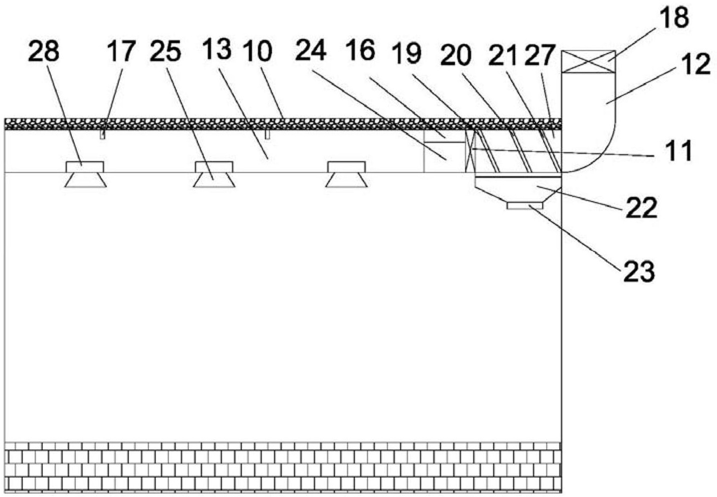 FIG. 1 — Schematic structural view of the tunnel ventilation device (transverse structure)
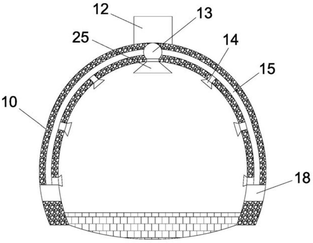 FIG. 2 — Schematic structural view of the tunnel ventilation device (front structure)